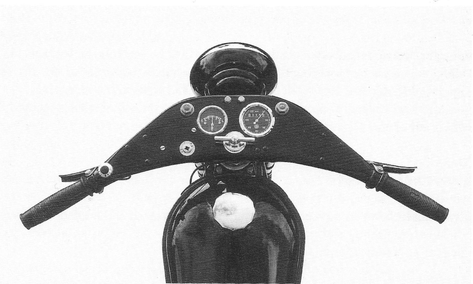
| Handlebars, etc. Handlebars The handlebars of the 1934 model are made of 2 mm pressed steel sheet. The top is totally flat and has twist grips for controlling the throttle and the lights, levers for front brake and clutch and a combined ignition and a light switch. In addition, the handlebars are a dashboard for the ammeter and speedometer. The retainers for the light and throttle twist grips, and the brace for the throttle valve’s Bowden cable, are riveted to the handlebars. The rivet heads are visible on top of the handlebars. Up to No 1400, the visible heads of the rivets have a diameter of 7.5 mm, later of 8.5 mm. The light switch is attached to the handlebars with 5 mm x 9 mm nickel plated bolts with cylindrical heads. Therefore, the bolt holes for attaching the switch are not countersunk. The handlebars are attached to the head tube of the telescopic fork with a threaded plug, 19 mm across flats.
Handlebars
90.
|
|
Ignition Switch Surround The ignition switch surround is round and marked A, P and K. A for Off (“Afbrudt”), P for Parking (Parkering) and K for Run (“Kørsel”). It has slots, allowing the key to be removed in positions A and P only. Hand grips Both hand grips incorporate twist grips, the lights being operated by the left hand grip and the throttle by the right hand grip. The handles were probably painted black. The hook on the throttle handle for the throttle valve is smaller than with later models. The twist grip rubbers are slightly barrel shaped; they have a lump at the end and have the NIMBUS name in capitals. Levers The levers for clutch and front brake are made of 2.5 mm chrome plated steel sheet and are fitted to the handle bars with 10 mm pivots, fastened with 6 mm x 5.5 mm special bolts with washer. The levers were probably painted black on the inside. Switch The switch, which is made of red/brown “NOKAIT”, like all later models consists of the ignition and the light switch. The light switch is operated with the left twist grip. All bolts for the switch are nickel plated and have a cylindrical head. Push button for the horn The push button for the horn is made by “Bosch” and has the code number SSH506/lz. The switch is made of nickel plated brass and has a screwed lid with crosswise grooves. The push button is made of black Bakelite with the “Bosch” logo.
91.
|
|
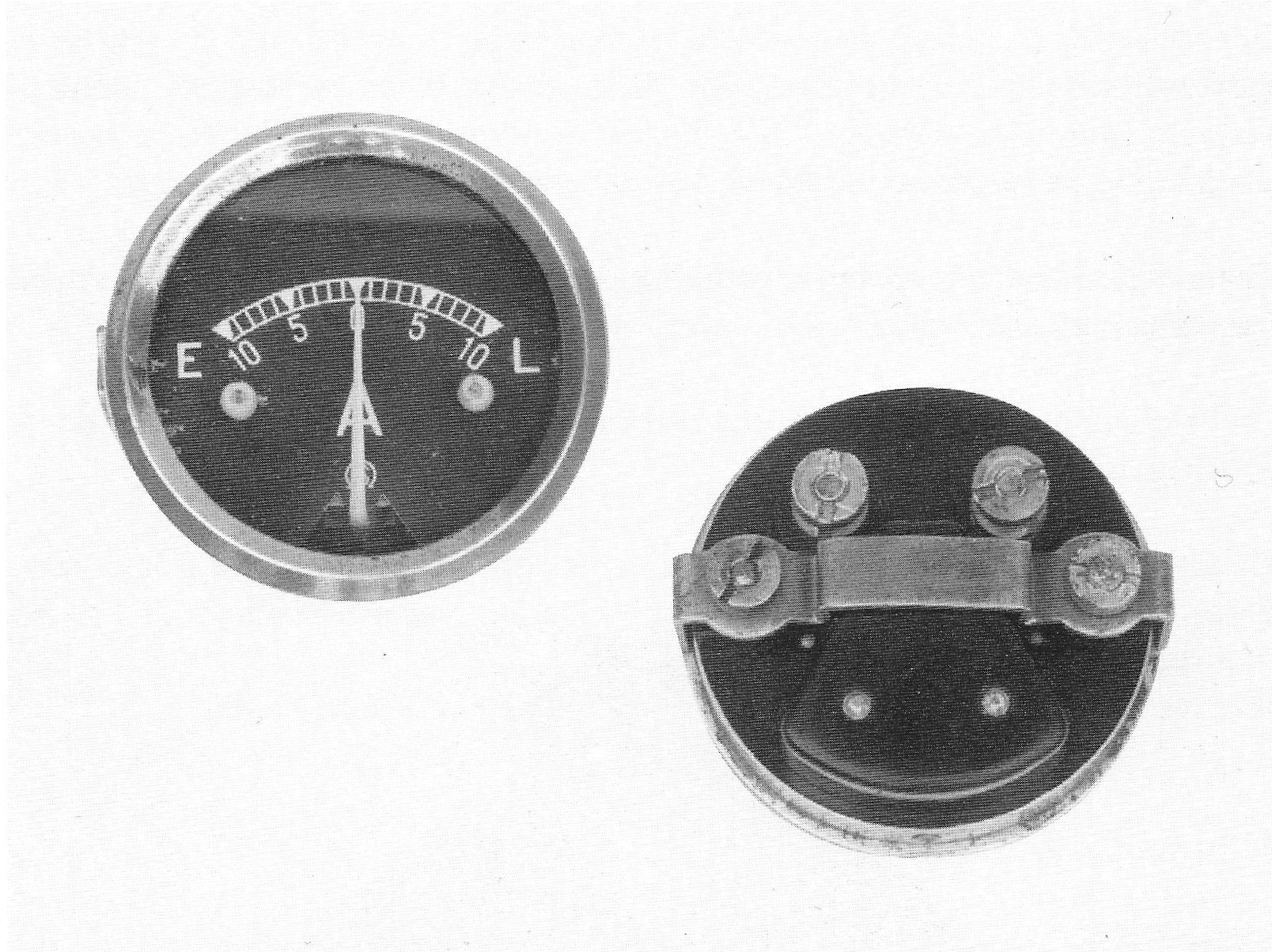
Ammeter The ammeter has a diameter of 52 mm with a 6-0-6 amp scale for charging or discharging. The first models were provided with a Schoeller ammeter produced by “SCHOELLER & CO, FRANKFURT AM MAIN”. Later, presumably by the end of 1934, they switched to 10 amps. “VDO” ammeters.
“Schoeller” ammeter, with the incorrect dial, because the numbers have to be positioned above the scale. The large black rubber stoppers, intended to prevent damage at extreme indications, are specific for this model.
The ammeter gave rise to many problems. The needle moves during running and is mechanically weak. After the introduction of the voltage regulator with No 1501, many riders found it difficult to interpret the ammeter, as a zero reading with fully charged battery often gave the impression that the dynamo was not charging. The ammeter was replaced by a charge lamp from No 2401.
92.
|
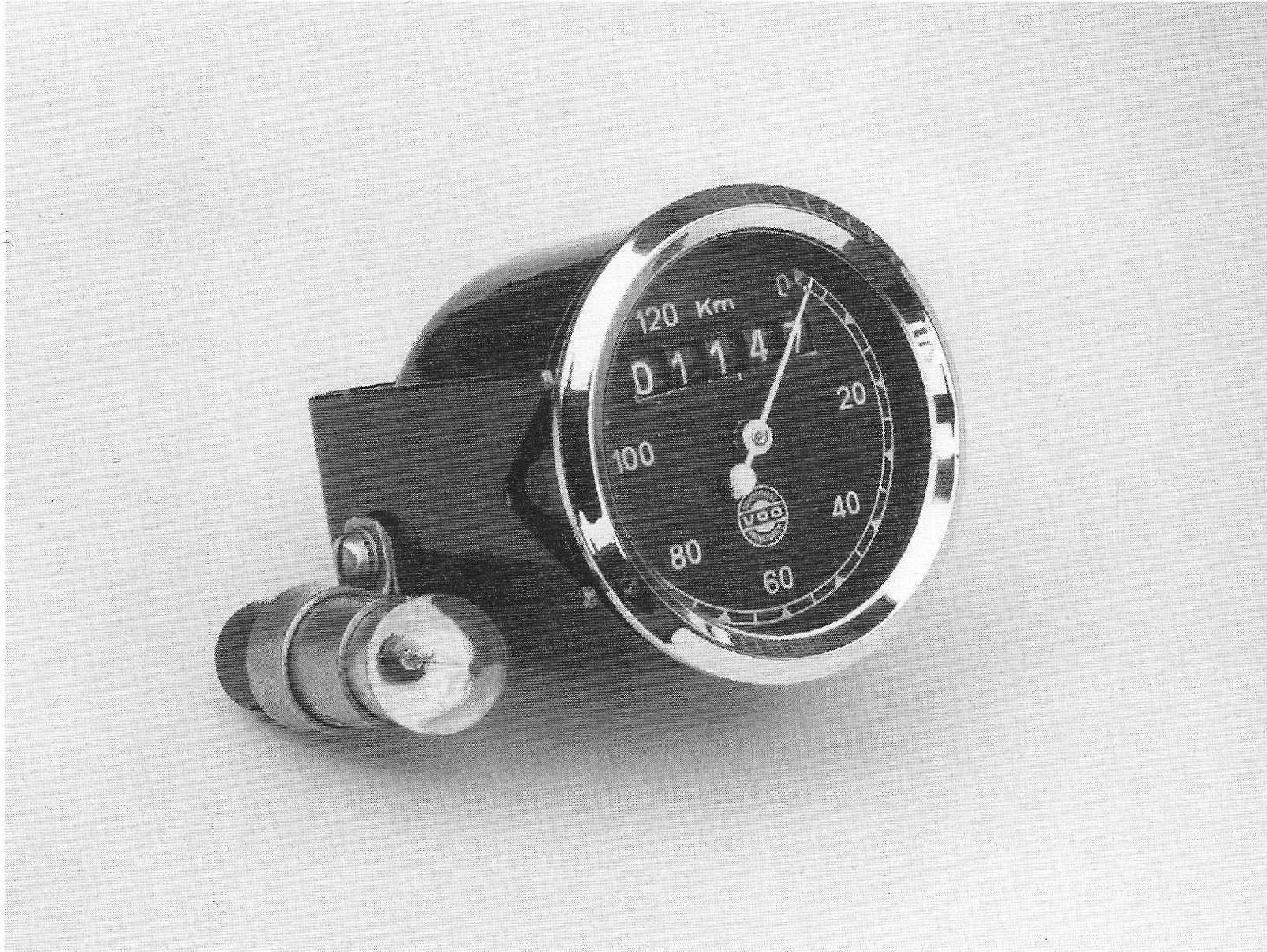
| Speedometer
The speedometer is a 60 mm “VDO” with a
17 mm threaded connection for the cable.
The needle has a round counter weight.
The reduction ratio and month and year
of manufacturing are stamped at the bottom, e.g. W 1.5 2 34.
The speedometer is attached to the handle bars by means of a U shaped brace on which a lamp is fitted for illuminating the speedometer and ammeter.
Speedometer with brace and lamp. 93.
|