Cam shaft, rockers, ignition, etc. Camshaft housing
The 1934 model camshaft housing can be
recognised by the support surfaces being designed with hollow-shaped
sides, so that they match the engine block around the attachment
bolts, whereas the drain hole for the return oil has a rectangular
shape. From No 2051 the distributor was fitted with a graduated adjustment scale, with its bolt serving as an earth connection.
48.
|
|
Nearly all early camshaft housings have been modified in the course of time, either by having a threaded hole for the earth bolt or alternatively, the ignition adjusting screw being used for the same purpose. Rockers All rockers are the same up to No 7500. The part of the rocker protruding into the camshaft housing is 5 mm wide. This width was increased to 7 mm from No 7501 onwards; simultaneously the contact profile with the cam was heightened and more curved. Rocker guides
Rocker guides are the same until No
10300. The guides have a fixed cover without a gasket around the
rockers. It can be seen from the patent description of March 1933
that initially a felt gasket or similar was planned. As far as we
know, this gasket was never fitted to motorcycles put into mass
production. Camshaft The camshaft is fitted in the pressure lubricated bearing bushes of the camshaft housing and is the same for all models, with the later camshafts marked “NIMBUS”. Camshaft gearwheel
The camshaft gearwheel remained
unchanged from No 1301 until No 3000. On the camshaft, four cams forming a square are fitted, including centrifugal weights, for ignition advancement. The square with the four cams is locked in position
49.
|
| by means of a flat brass securing plate with long brass pins. Starting with No 2051 the locking plates were made of steel sheeting with a step at both ends. Simultaneously shorter pins were fitted.
1934 camshaft housing with camshaft.
The following article from INGENIØREN (the engineer) of September 29, 1934 is probably the best contemporary technical description of the 1934 Nimbus we have.
50.
|
|
|
|
[Translation of page 51]
MACHINE TECHNIQUE Editor: P.A.Christensen, M. Ing. F. September 29, 1934 Responsible for the press law IV, 7. Page. 49 – 56 Content: The new Nimbus motorcycle – Does Denmark need to have a trawler fleet? – The 25th anniversary of the Swedish union for heat and sanitary technique. By department engineer O. Juel Jørgensen. – Propulsion friction with ships. – Heating technique. – Personal. – New ships.
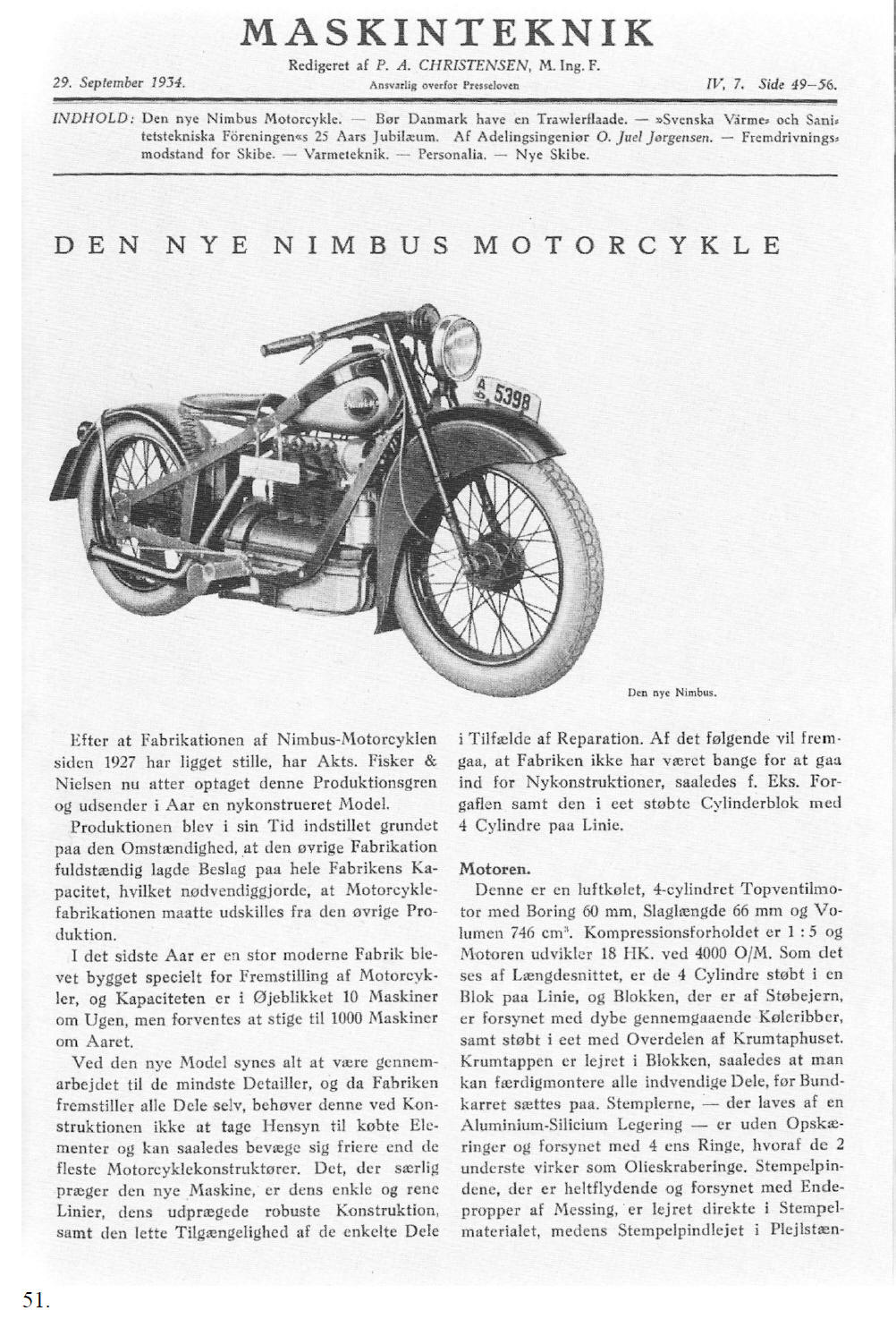
THE NEW NIMBUS MOTORCYCLE
[Photograph] The new Nimbus
Motorcycle production
ceased in 1927, and A/S Fisker & Nielsen have recently commenced
production again and will bring a newly designed model to the market
this year.
The engine This is an air cooled 4 cylinder engine with overhead valves and with a bore of 60 mm, a stroke of 66 mm and a cubic capacity of 746 cm³. Compression ratio is 1:5 and the engine develops a power output of 18 hp at 4000 rpm. As shown at the longitudinal section, the four cylinders have been cast in line as one unit and the block, which is made of cast iron, is provided with wide, continuing cooling fins cast as a whole with the upper part of the crank case. The crank shaft runs in bearings, fitted in the block, allowing all internal parts to be assembled, prior to fitting the oil pan. The pistons are made of an aluminium-silicon alloy and have no slits and are fitted with four equal piston rings of which the bottom two serve as oil control rings. The gudgeon pins, which are fully floating and fitted with brass end caps, are directly fitted in the piston body, whereas the gudgeon pin bearing bushes
51.
[End of translation of page 51]
|
|
|
|
[Translation of page 52]
[Drawing]
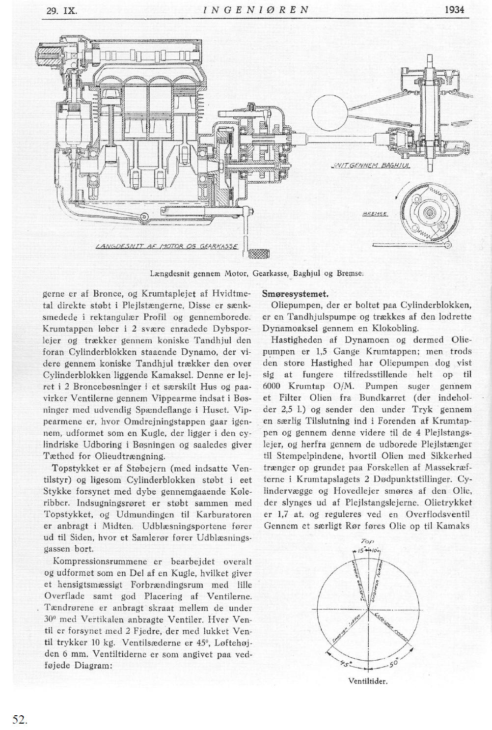
CROSS SECTION OF THE REAR WHEEL BRAKE LONGITUDIAL SECTION OF THE ENGINE AND GEAR BOX
Longitudinal section of engine, gear box, rear Wheel and brake
are made of bronze. The big end bearing
is made of white metal, cast directly into the piston rods. These
are drop forged in a rectangular profile and have a longitudinal
bore. The crankshaft runs in two heavy single track deep grooved
ball bearings and drives the dynamo, which is fitted at the front of
the engine, by means of conical gear wheels which, in turn, drives
the overhead camshaft through conical gear wheels. The cam shaft
runs in two bronze bearing bushes fitted in the separate housing and
operates the valves by means of rockers, which are fitted in bearing
bushes with external flanges, fitted in the camshaft housing. At
the pivot point, the rockers are ball shaped, and are supported in
the cylindrical bore of the bearing bush, thus forming a seal
against leaking.
[Drawing at the RH side] Valve timing diagram
The lube oil system
The lube oil pump, which is
bolted to the cylinder block, is a gear wheel pump, driven by the
vertical dynamo shaft, through a claw coupling. 52. [End of translation of page 52]
|
|
|
|
[Translation of page 53]
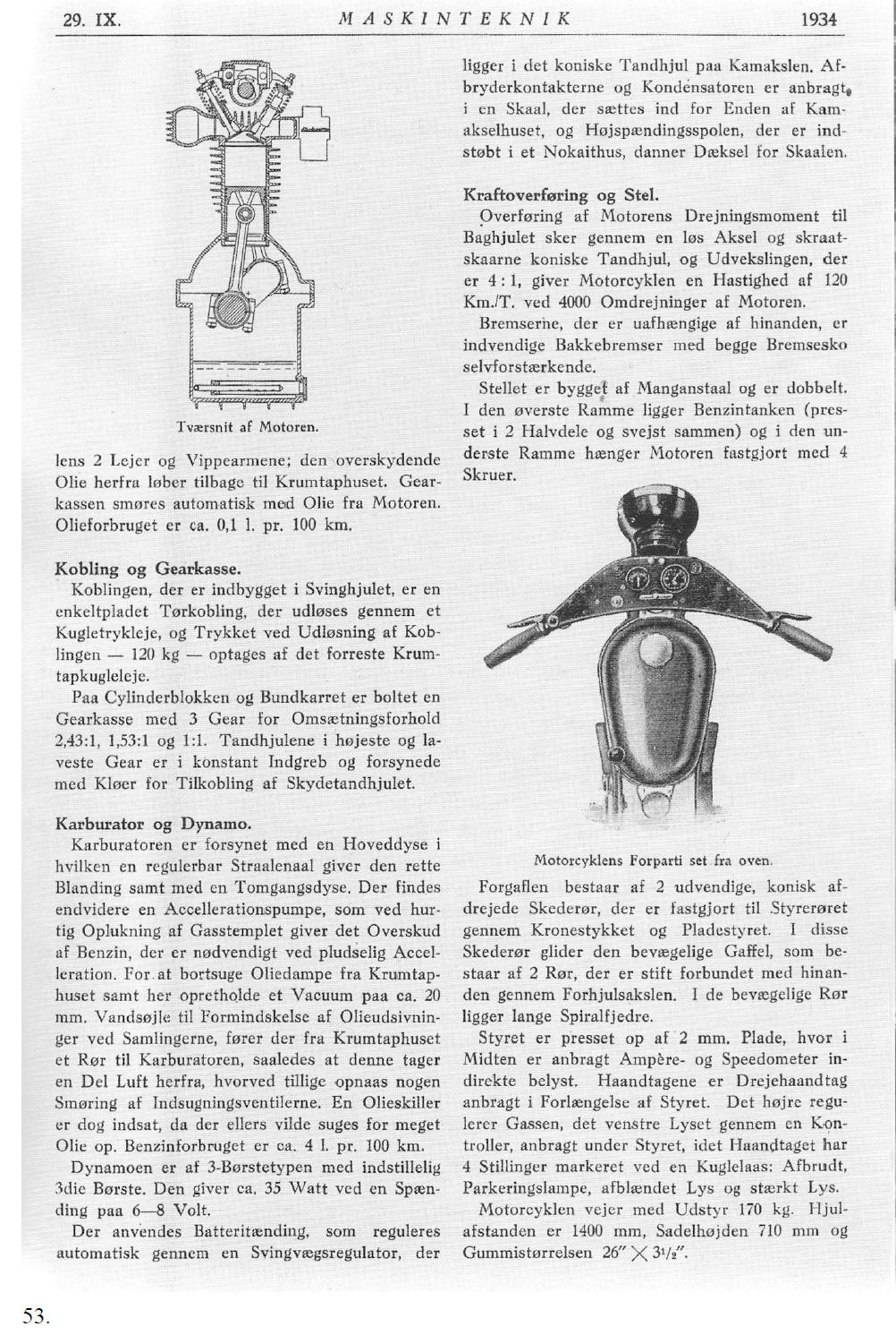
[Drawing] Cross section of the engine.
cam shaft bearings and the rockers; the excess oil flows back to the oil pan. The gear box is lubricated automatically with lube oil from the engine. The oil consumption is about 0.1 litres per 100 km.
Clutch and gear box
Carburettor and dynamo
Transmission and frame
[Drawing] Top view of the front section of the motor bike
The front fork consists of
two outer conically milled fork tubes, fitted to the head tube by
means of the yoke and the flat steel handle bars. The fork tubes
contain the movable front fork, consisting of two tubes, tightly
connected to each other through the front wheel. The movable tubes
contain long spiral springs.
53. [End of translation of page 53]
|
|
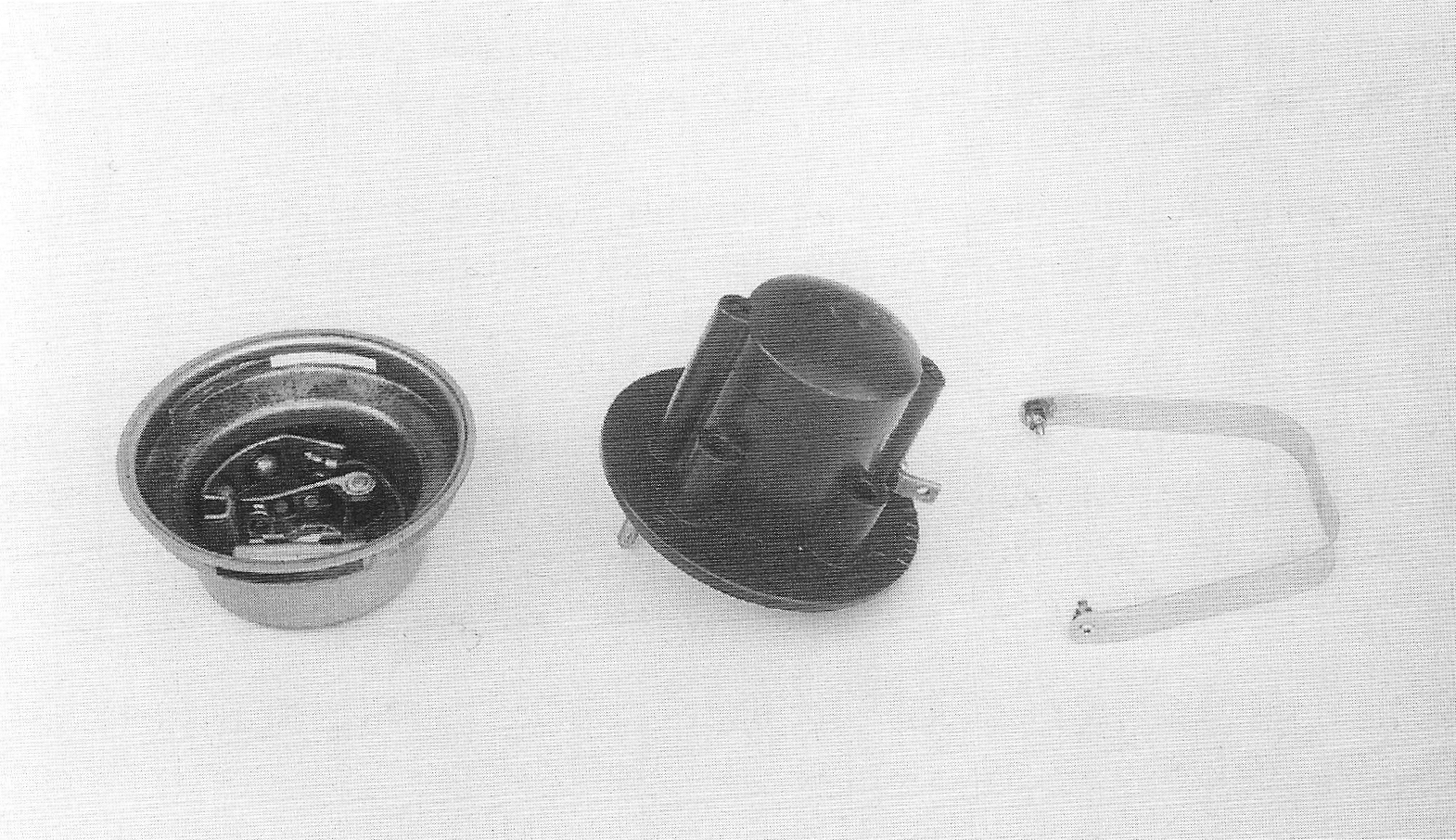
Ignition coil, distributor housing, brace
The ignition coil is combined with the distributor in the brown, bakelite housing. There is a graduated scale at the bottom of the flange of the housing for the adjustment of the ignition and has the characters “T” and “S” for advance and retard ignition respectively. The ignition is adjusted by rotating the ignition coil relative to the notched mark at the bottom of the camshaft housing. The 1934 ignition coil is identified by the sharp transition between the housing and the flange of the ignition coil and by the coil housing and cover being flush. Because of problems caused by water intrusion, the cover has been provided with a collar, starting with number 2050. The earliest ignition coils had their 6 volt leads directly screwed onto the coil’s housing. This could however result in cracking of the housing when fastened too tightly. The problem was solved, probably by the end of 1934, by fitting a strong brass angled profile for connecting the leads. The ignition coil is attached to the distributor housing by means of a nickel plated brass brace. The brace swings in the distributor housing by means of two pins with thinner ends, which can slide in long slits in the ignition housing; the amount of rotation is limited, in relation to adjustment of the ignition.
The slits in the 1934 housing are
approx. 44 mm long, their effective length is approx. 34 mm because
the distributor housing has a soldered brass strip on the inside
which serves as a stop. It is unclear whether or not the earliest
ignition housings were provided with the soldered strip. This was
probably not the case. The earth connection of the distributor housing runs through the pins of the ignition coil brace. This proved to be an unreliable connection and therefore starting with number 1526, an earth connection was made by means of a 4 mm finger screw, on the side of the camshaft housing. Simultaneously, the slits in the distributor housing were lengthened to 20 mm, which limits the angle of rotation of the ignition coil to approximately 20º.
After having ridden with the early types
of distributor housings for some time, they became stuck and were
difficult to rotate when adjusting the ignition.
54. |
| The distributor’s rotor is made by “Bosch, type Z.V.T. 23/1 Z”. The make of condenser is “Hydra”.
Distributor housing, ignition coil and brace
H.T. Leads, spark plug caps, sparkplugs The H.T. leads are made of blank wire, insulated with rubber, wrapped and lacquered black. They are fitted with brass terminals and brown, bakelite caps. The H.T. leads are secured with a piece of oiled cardboard, wrapped in linen insulating tape and lacquered black. The H.T. leads are secured in the caps with a slotted bush, which at the same time connects the cap with the spark plug. The caps have been unchanged during the entire production period, but as of No 7500 the bushes were replaced by a bush containing a sprung wire serving as a lock. The H.T. ignition leads are attached to the camshaft housing with a single brace without screw. The spark plugs are “Lodge, type H.D. 14”.
55.
|