|
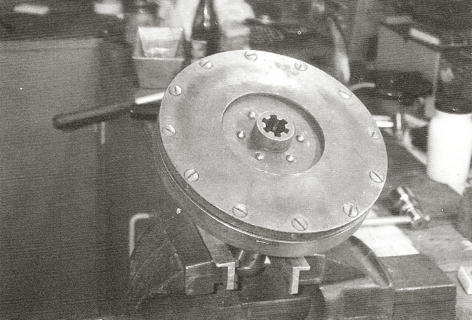
Clutch, Gearbox Clutch The clutch, which is fitted in the flywheel, is of the single dry plate type. It has 12 springs exerting a total pressure of 120 kg and is operated through the gear box by a push rod with thrust (ball) bearing. Pressure and counter pressure plates are unlined and therefore have no holes for rivets.
38.
|
|
The earliest pressure clutch plates are made of 2 mm steel plate. This thickness was increased to 2.5 mm during 1934. The edge of the counter pressure plate is not bevelled and the central hole is 95 mm in diameter. Starting with number 1550 the clutch had a sprung hub. In order to create space for the springs, the diameter of the hole in the counter pressure plate was increased to 116 mm.
1934 clutch. Please note that the flange of the clutch hub is hidden behind the clutch plate and therefore cannot be seen.
The 1934 clutch plate is made of 2.5 mm steel plate and has 6
straight slits. The lining is riveted on both sides of the clutch
plate. The counter pressure plates have, as mentioned, a punched central hole with a diameter of 95 mm. The punched-out circle was used by F&N as a cover plate at the front of the crank case housing.
39. |
|
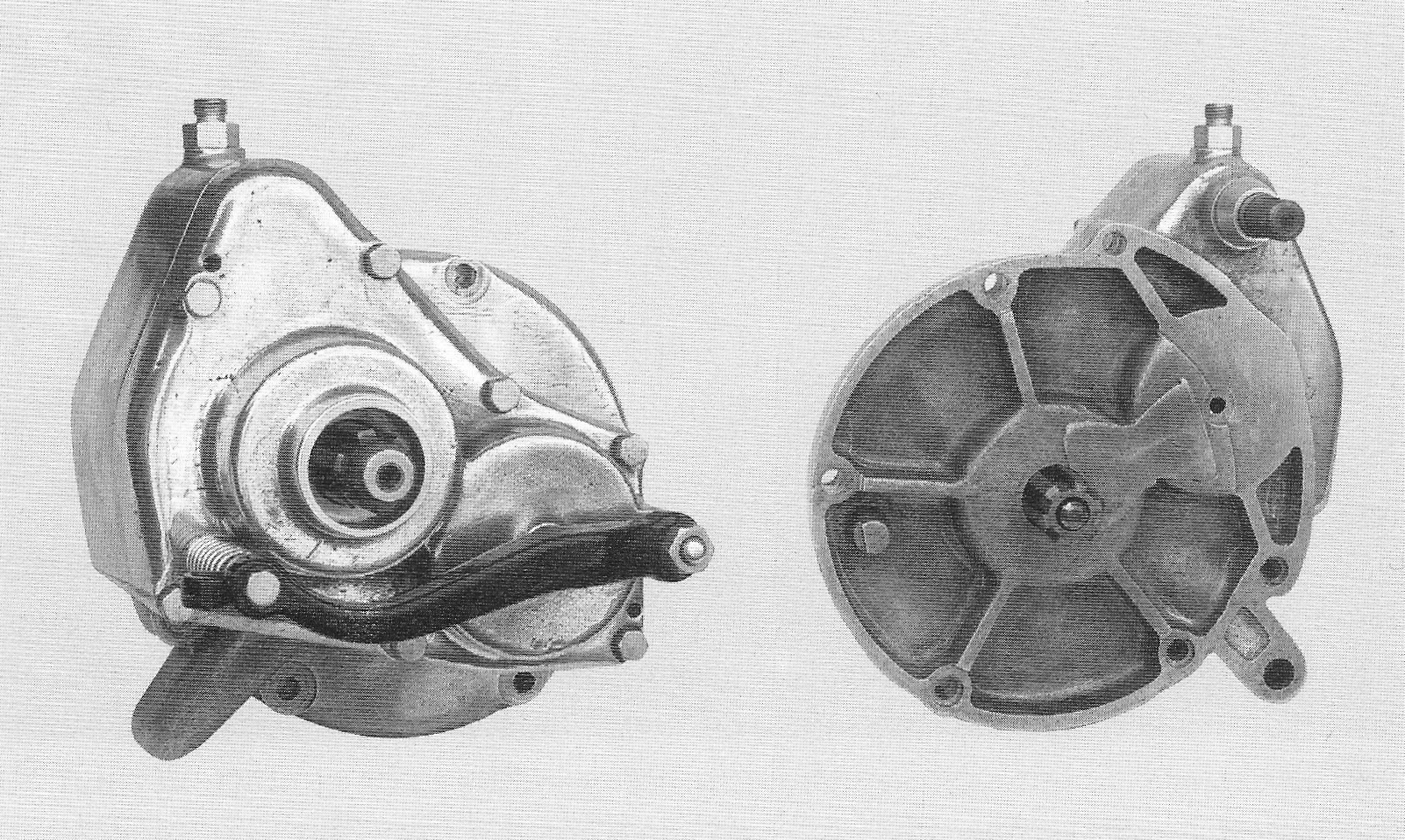
Gearbox The 1934 gearbox at first sight looks like the later models up to No 7500; yet there is a long list of differences, both internally and externally.
The gearbox does not have the raised section around the second bolt
hole from the top which was introduced later.
Gearbox housing
The cover of the gearbox has a 15 mm high collar without a cork
gasket for the solid drive shaft and its bearing housing has rounded
edges.
40.
|
|
The 1st gear cog has 34 teeth and the
3rd gear cog has 24 teeth both having strong rectangular gear claws.
The 2nd gear cog has 29 teeth and has corresponding
rectangular slots.
The gearwheels or cogs of the main shaft have 14, 19 and 24 teeth
for 1st, 2nd and 3rd gear respectively. The bore in the main shaft
for the thrust bearing of the declutching rod is shorter than those
of the next models, because no cork gasket has been fitted around
the declutching rod, as the later models have. The gear lever gate has four notches for the 1st, neutral, 2nd and 3rd gear respectively. The declutching rod is controlled by an 8 mm bolt with a small 10mm hexagonal head.
The rectangular gearwheel claws of the 1934 gearbox have proven to
wear out rather quickly, resulting in frequent popping out of 3rd
gear. The fact that the problem was widespread can be concluded from
the large number of 3rd gearwheels with heavily worn out
gear claws or claws that have been abused with a rotating grinding
stone or an angle grinder. The 1934 gearbox is pressure lubricated with oil from the lube oil pump through the lube oil pipe mounted in the right hand side of the crankshaft housing and entering into the bore of the gearbox shaft. The bearing bushes of the 1st and 3rd gearwheel are lubricated through the holes in the gearbox shaft, after which the oil runs down, resulting in splash lubrication for the other parts of the gearbox. The remaining oil flows back through the drain ducts to the crank case. As stated previously, an unrestricted oil flow can be jeopardised when the oil pressure is not high enough. Many 1934 gearboxes show 41. |
|
Gearwheels of the gearbox, main shaft, lay shaft and shifting shaft.
modifications to improve lubrication, e.g. increasing the oil sump
level by fitting a vertical copper pipe in the oil drain hole and
quite often primitive oil cups have been ground around the mouth of
the oil duct in the gearbox shaft.
42.
|