| Frame, Seat, Exhaust pipe, etc. Frame
The 1934 frame can be recognised
initially by the relatively thin head tube which has, at the lower
end, a flat steel bar reinforcement welded onto it. The head tube is
connected to the frame by means of wings, welded onto the front and
riveted to the frame. The very first frames did not have a head tube
with the welded flat steel-bar reinforcement. Even with the flat
steel-bar reinforcement, the head tube was still much too weak for
daily use, consequently, from frame number 1550 a stronger head tube
was produced which was reinforced with extensions at both sides,
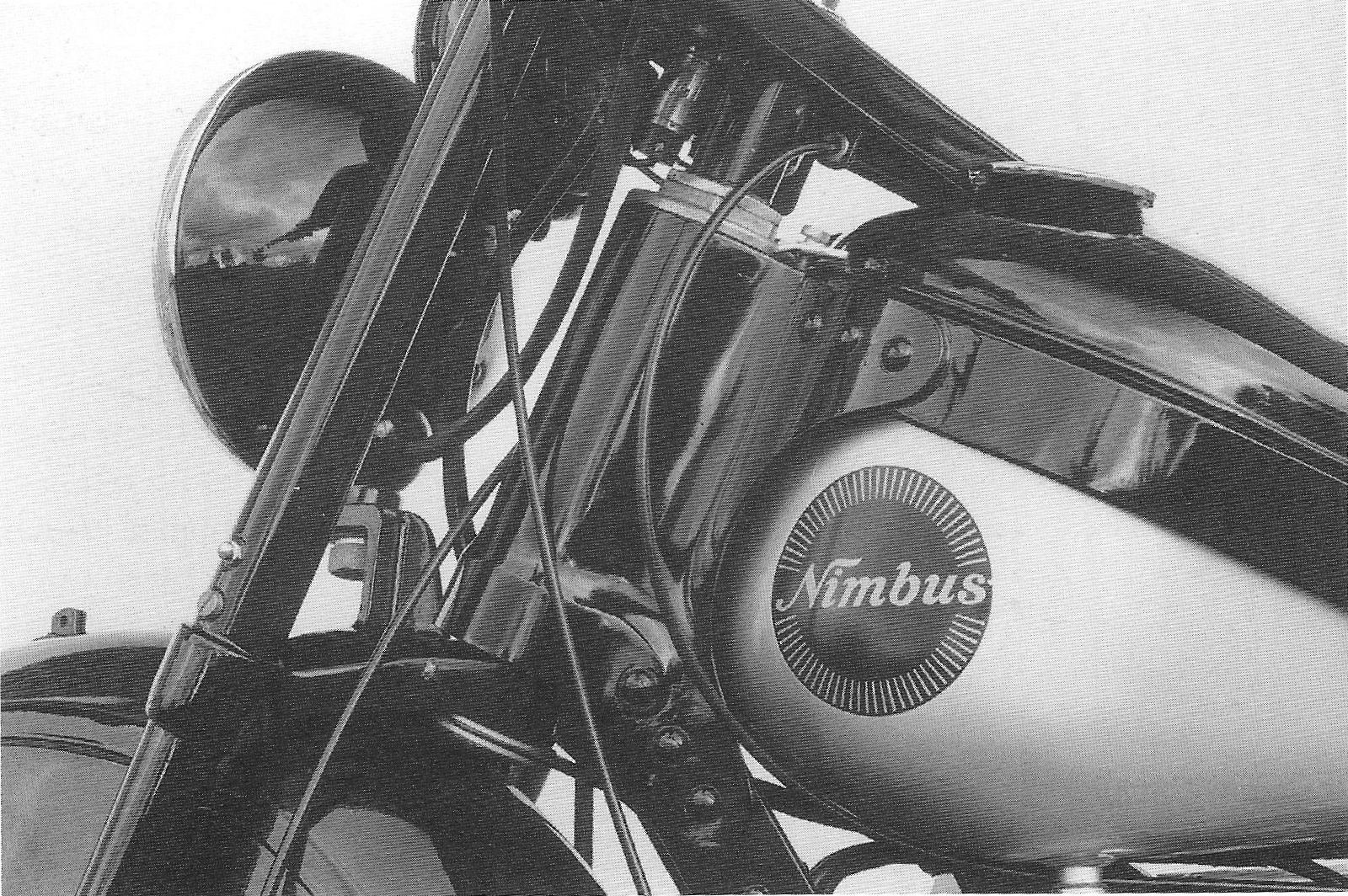
forming a cap around the head tube. The frame plate behind the tank has a cut away for the gear lever. In addition, there are two threaded holes for the clamp to fasten the tank, and two holes for the frame number plate and the brace for the electrical wiring. A threaded 8 mm hole for fastening the heat shield is located on the righthand side between the foremost rivets of this frame plate.
62.
|
|
Head tube with reinforcement
The reinforcing plates for the rear
wheels are attached to the frame by means of rivets with a spherical
head; in 1935 the rivets were countersunk on the inside. The space
between the two plates is filled at the front by welding in a piece
of flat bar. The rear mudguard has a small hole for the rigid drive shaft and a shelf for the battery riveted onto it.
Starting with number 1400, holes were provided for the wires and the stop light switch on the right side of the rear mud guard.
63.
|
|
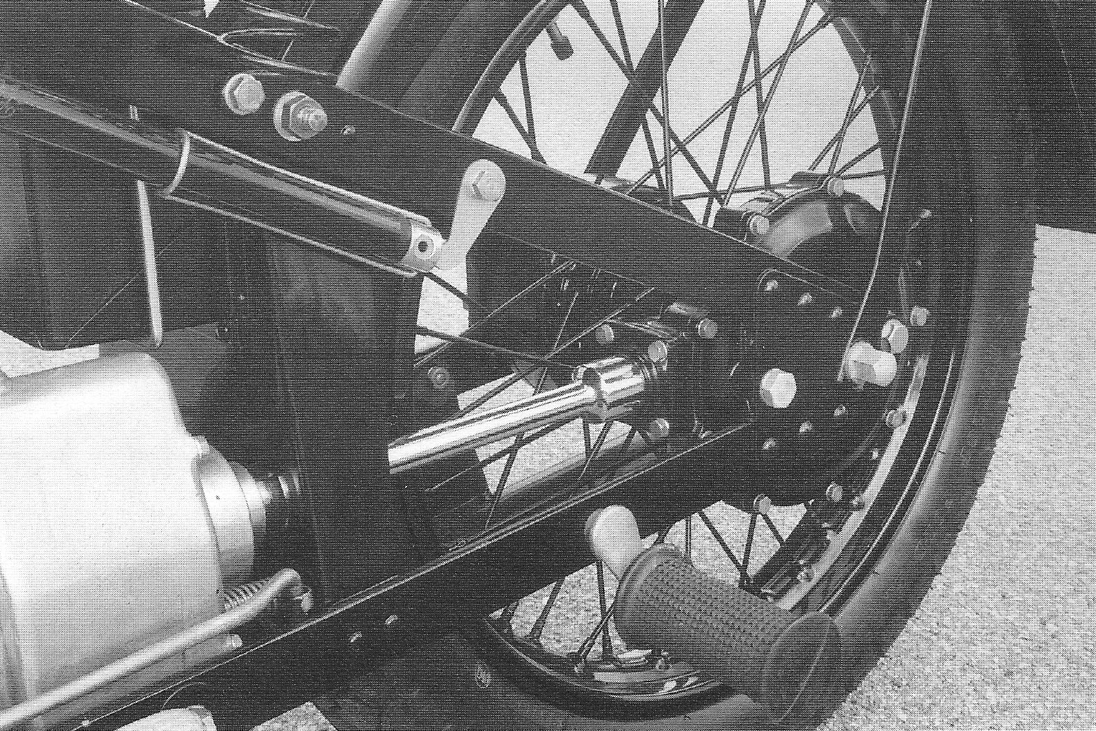
Frame, details of the rear wheel The flat steel of the frame, the seat support and the reinforcement of the mud guards are oftenmarked “FAGERSTA”, “0,35” and a swastika. “FAGERSTA” is the name of the Swedish steel company, “0,35” refers to the steel quality which is hardened and tempered with a carbon content of 0.35%. The swastika was the company’s logo at that time.
64.
|
|
|
|
66.
|
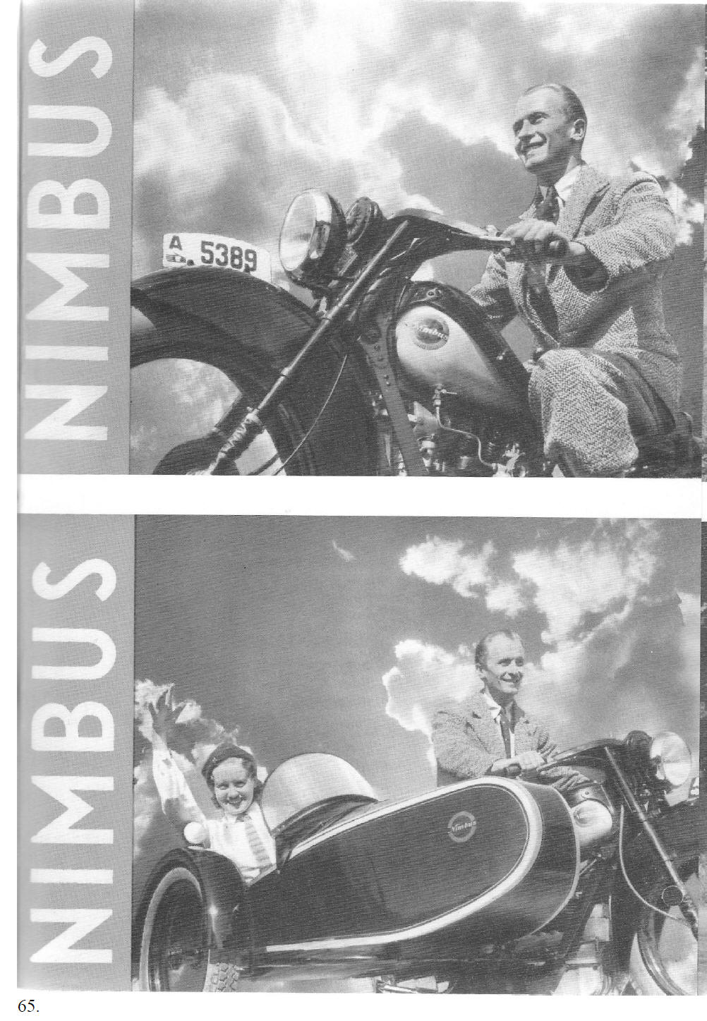
| [Translation of page 66] [Photograph] Why should you buy a MOTORCYCLE?
Good question, why should you buy a
pedal [Photograph] Every child in the country knows NIMBUS.
The vintage models of Denmark’s most
popular motorcycle are still in the ownership of numerous customers,
who, before production ceased in 1927, bought themselves one of
these long lasting machines. Nimbus - Denmark’s motorcycle. 66. [End of translation of page 66]
|
|
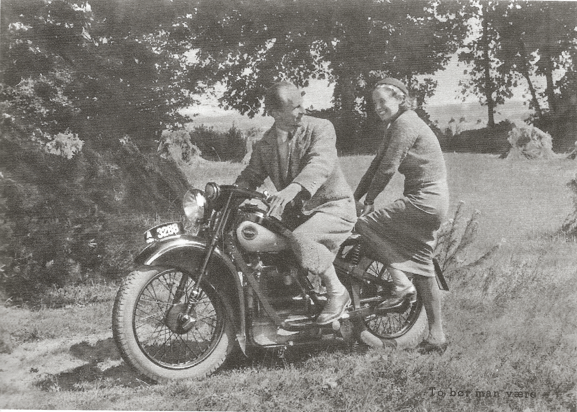
Two people, like it should be
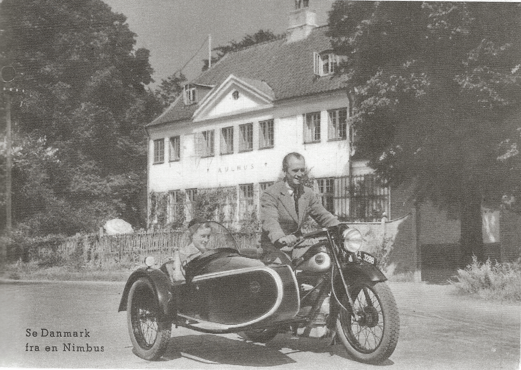
See Denmark from a Nimbus.
67.
|
|
|
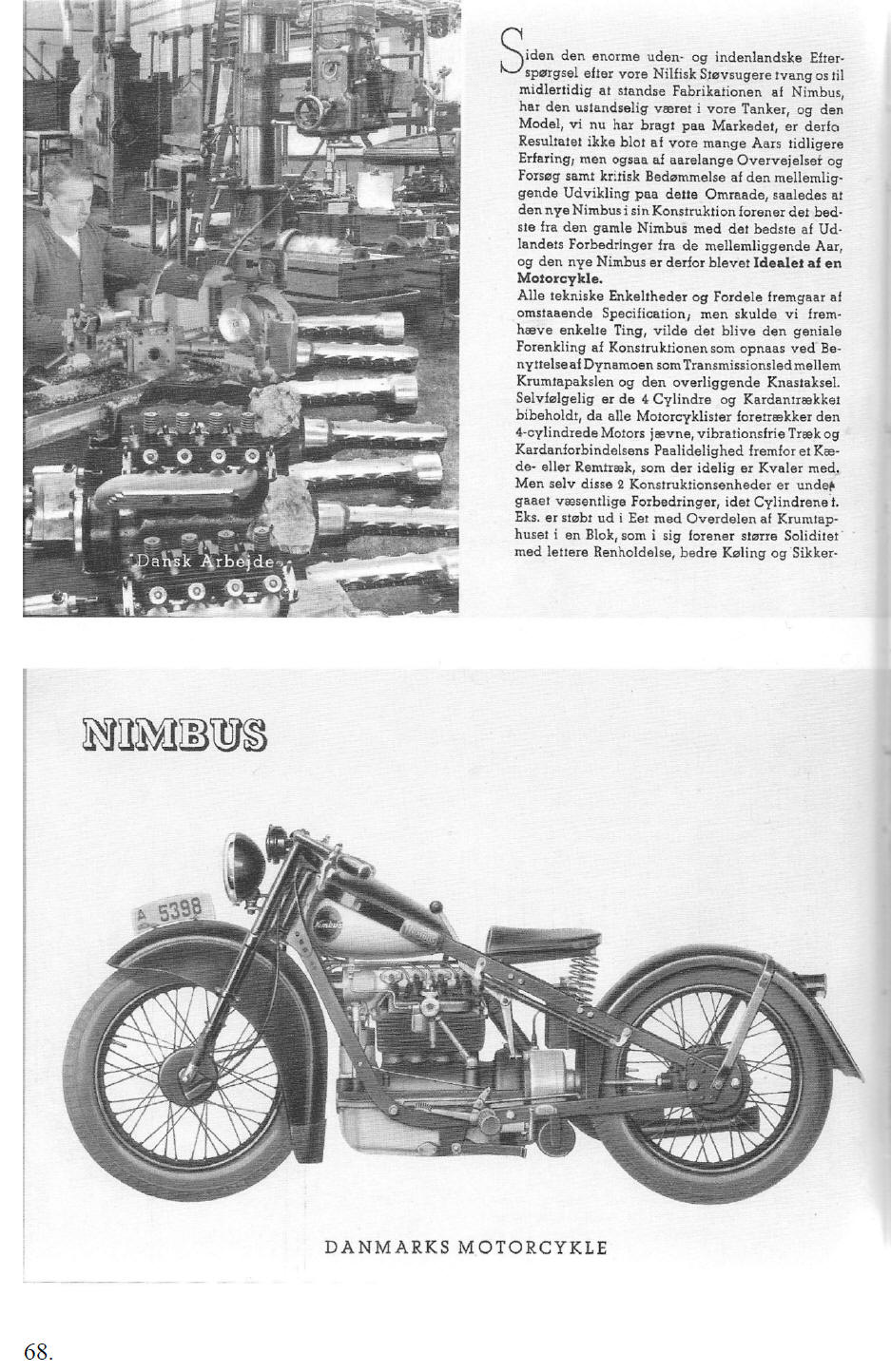
| [Translation of page 68] [Photograph] Danish engineering works
When the high demand for our Nilfisk
vacuum cleaners, from both abroad and at home, forced us to
temporarily cease production of the Nimbus, it has constantly been
in our thoughts and the model, which we have put on the market now
is the result of, not only our earlier years of experience, but also
of many years of research and development, such as the critical
judgement of the industry developments which have taken place in
this field. So the construction of the new Nimbus combines the best
of the old one with the improvements made during the intermediate
years. Therefore the New Nimbus has become the ideal motorcycle.
[Photograph] NIMBUS DENMARK’S MOTORCYCLE
68.
[End of translation of page 68]
|
|
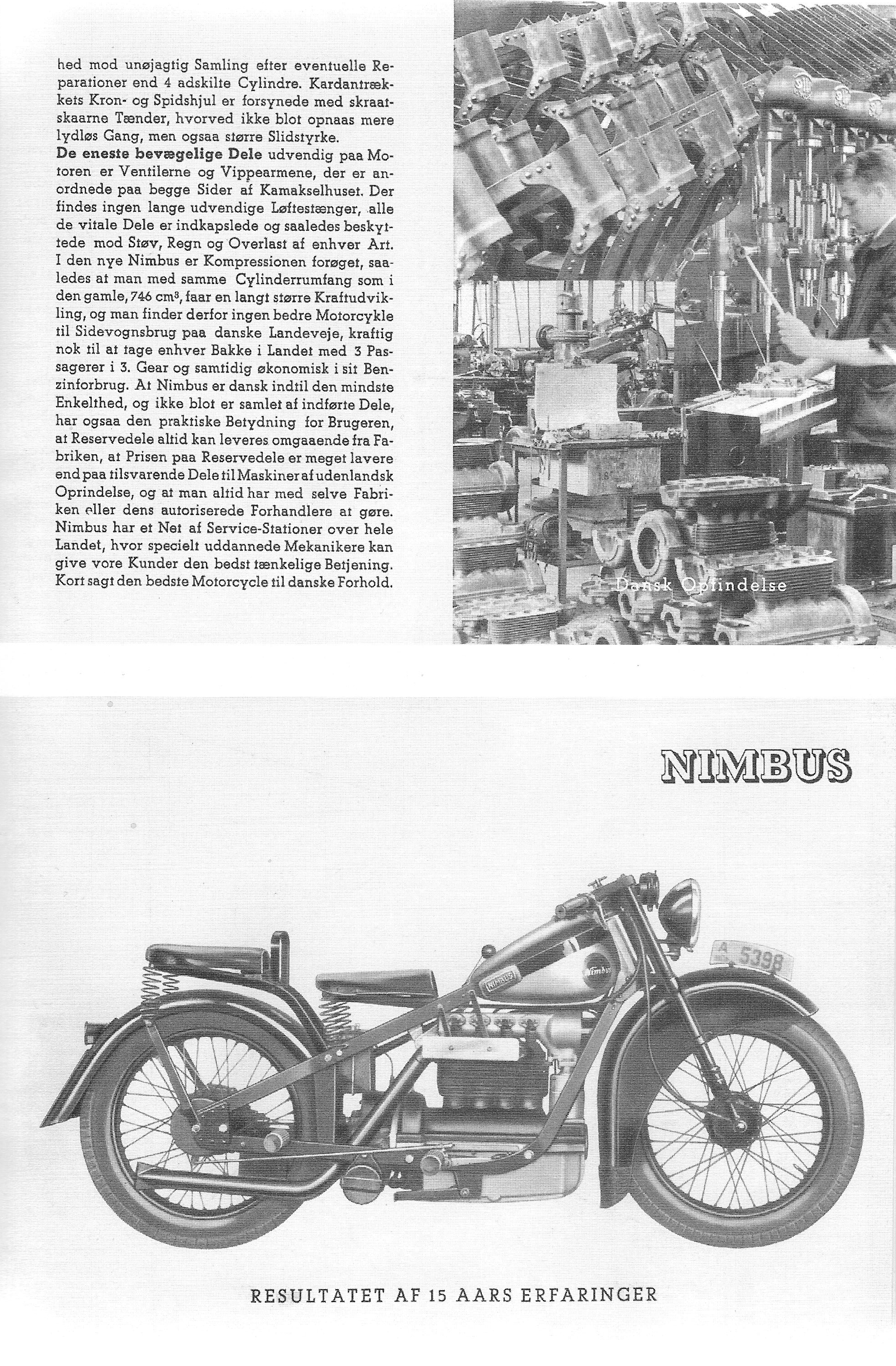
RESULT OF 15 YEARS OF EXPERIENCE 69.
|
|
[Translation of page 69]
against incorrect assembly after
possible repairs, than with four separate cylinders. [Photograph] Danish invention [Photograph] RESULT OF 15 YEARS OF EXPERIENCE
69. [End of translation of page 69]
|
|
|
|
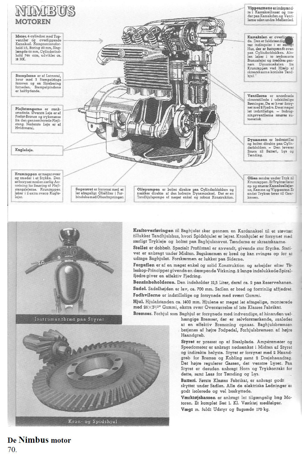
[Translation of page 70] The Nimbus engine [Clockwise]
Engine.
Pistons are made of alloy, with three piston rings at the top and one oil control ring at the bottom.The gudgeon pins are fully floating. The connecting rods are drop forged. The small end bearing is made of phosphor bronze and is lubricated under pressure through the bore in the connecting rod. The big end bearing is made of white metal. Ball bearings The crankshaft is very heavy and forged in one piece. It has a unique design for the lubrication of the big end bearings. The crankshaft rotates in two heavy duty ball bearings. In order to drain the oil, the lube oil suction pipe is provided with an easily detachable lube oil filter. The lube oil pump is bolted directly to the cylinder block and is driven by the vertical shaft of the dynamo. It is a gear pump of simple, robust construction. The lube oil is fed under pressure to the crankshaft. Oil is also pumped via a pipe to lubricate the camshaft bearings, cams and rockers. Another pressure line feeds the oil to the gearbox. The dynamo is placed vertically and is directly fitted to the cylinder block. It supplies electricity to the battery, the lights and the ignition. The valves are placed at an angle in exchangeable guides and have two springs per valve. The valves are easily adjusted. The inlet valves are lubricated automatically via the carburettor. The overhead camshaft is fully enclosed in a dust proof housing, located on top of the cylinder block. The shaft runs in two bronze bearings, lubricated under pressure, and is driven from the crankshaft through the dynamo shaft by means of bevel gears. The rockers are fitted in the camshaft housing and transmits the movement of the camshaft to the valves.
|
|
[bottom part of the page]
The
transmission of power to the rear wheel takes place by means
of the drive shaft to the dust proof gear housing in which the drive
pinion runs. The crown wheel is fitted with a special thrust
bearing, tightened with bolts to the rear wheel hub. The teeth are
bevelled. The frame is double sided using special profile
steel, which gives increased strength. The stand is located in the
centre. The rear mudguard is wide and is hinged to assist in removal
of the rear wheel. The front mudguard has closed sides (valances).
70. [End of translation of page 70]
|
|
|
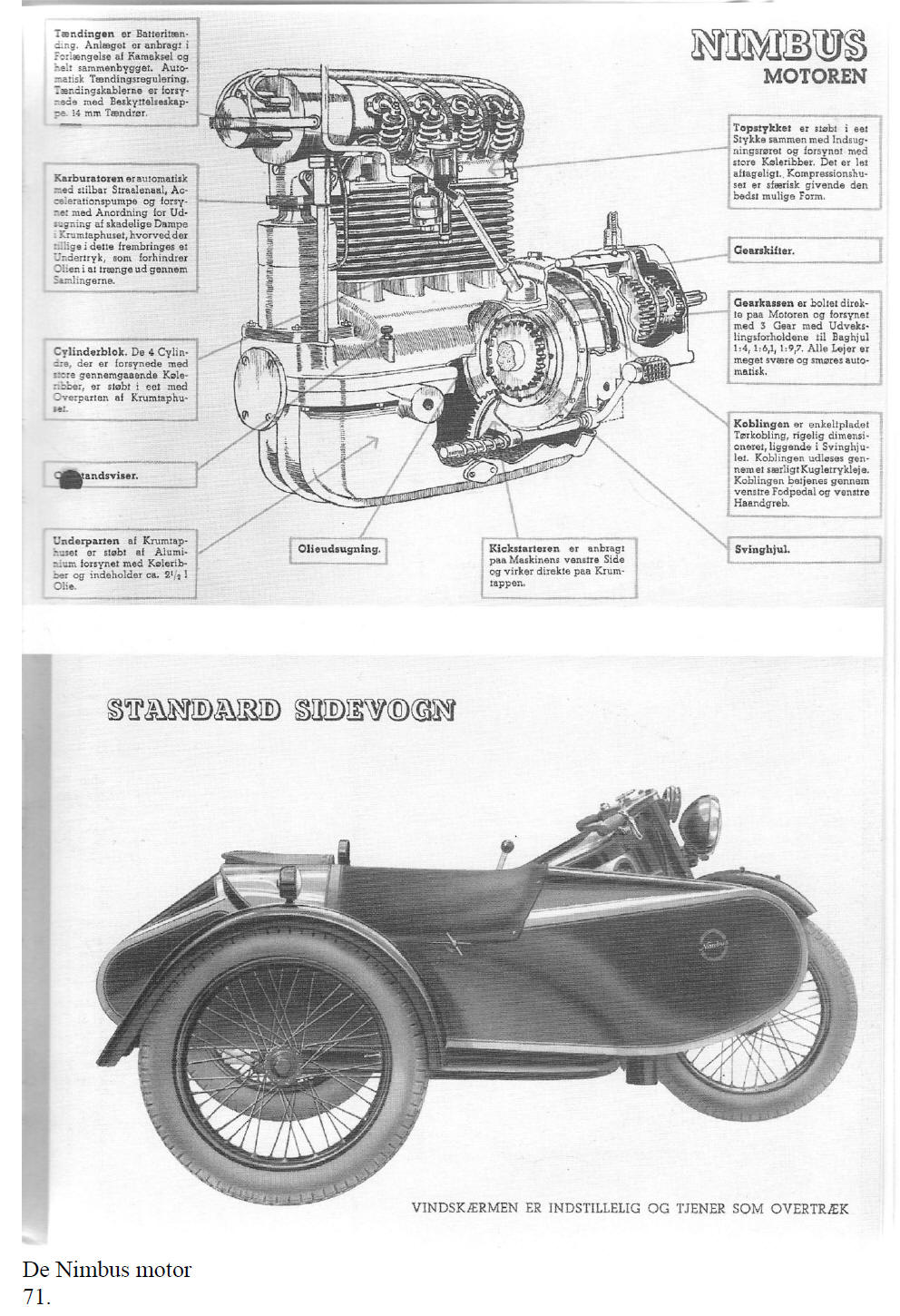
| [Translation of page 71] The Nimbus engine [Anti clockwise] The battery ignition unit is fitted in line with the camshaft and enables automatic timing. H.T. leads are fitted with protective caps and they connect to 14 mm spark plugs. The carburettor is automatic with adjustable nozzles and an acceleration pump. A pipe is fitted between the crankcase and the carburettor to extract hazardous fumes from the crankcase whilst maintaining a slight vacuum in the crankcase, thus preventing oil from leaking out between the joints. The cylinder block. The 4 cylinder block is cast in one piece, with large, cooling fins. The top section of the crankcase housing is also cast in one piece. Dipstick. The base of the crankcase housing is cast of aluminium, has cooling fins and contains 2½ litre of oil. Crankcase ventilation. The kickstarter is located at the left side of the machine and meshes directly with the crankshaft. Flywheel. The clutch is a single, dry plate clutch, suitably sized and placed in the flywheel. Declutching takes place by means of a special thrust bearing. The clutch is operated by the left foot pedal or the left hand lever. The 3 speed gearbox is bolted directly to the engine, with ratios to the rear wheel of 4:1, 6.1:1, and 9.7:1. All bearings are sturdy and are lubricated automatically. Gearshift. The cylinder head is cast in one piece, together with the inlet manifold and both have large cooling fins. It can easily be taken apart. The compression chambers are spherical, this being the ideal shape. Standard sidecar [Photograph] The windscreen is adjustable and also serves as a cover 71. [End of translation of page 71]
|
|
|
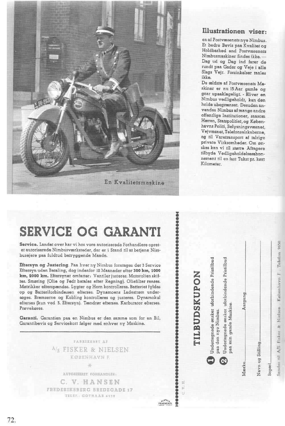
| [Translation of page 72] [Photograph] A quality machine The illustration shows:
One of the new Nimbuses used by the
Danish Postal Services. No better proof of quality and durability
can be portrayed than with the Nimbus motorcycles of the Postal
Services.
Maintenance and tuning.
three free service checks in the first 12 months, after
300 km, 1000 km, and 2000 km.
Manufactured by
*
DYBTRYK FRÆNKEL KØHVN C8869
…………………………………………………………………………………………………..
Offer coupon
Make____________________________ Year_____________________________ Name and profession__________________________________________________ Place of residence_____________________________________________________ Please send to A/S Fisker & Nielsen · Copenhagen · Telephone 9650
72. [Translation of page 72]
|
|
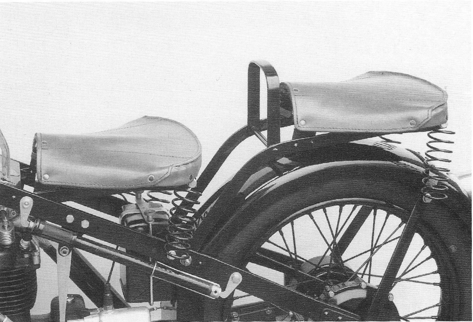
Seat The front seat is fitted inside the frame with bolts at the front and bushes immediately behind the frame plate near the tank, and at the rear with 5 mm or 5.5 mm coil springs. The springs have vertical eyes at both sides and are bolted directly to the frame and to the seat support. The front seat spring brace has 6 mm holes for holding the springs. The rear brace has 4 mm holes.
Seat and passenger seat, please note that the supports for the rear seat run inside the frame. Passenger seat The passenger seat is the same width as the front seat and is similar in shape. The flat steel seat supports hinge around the shoulders in the beads of the hinges of the rear mudguard and hence are fitted on the inside of the frame. The handgrip is a flat steel brace, fitted on the distance piece of the seat supports which is made of 12 mm round steel bar. The holes in the seat supports are drilled at the rear in the side supports of the seat, in similar fashion as the front seat. The front seat spring brace is riveted at both sides to the seat support, the rivets having a spherical head.
73.
|
|
The 1934 passenger seat is of poor design and construction. The seat is unstable and the handgrip is uncomfortable to hold. The construction was modified towards the end of 1934 or at the beginning of 1935.
The new seat is wider than the old one.
The side members of the seat run on the outside of the frame and are
reinforced with two flat steel bars crosswise. The holes for the
seat springs have been moved about 40 mm forward. The handgrip is
chrome plated round steel tube. Seat upholstery The upholstery of the seat, or seat cover as it is called nowadays, is made of synthetic leather. The fastening straps of the cover are secured with visible rivets.
Exhaust pipe The exhaust pipe is a black enamelled iron pipe with a flattened fish tail. The exhaust probably had no silencer, as F&N’s silencer drawings are dated 1/31/1935. The exhaust could be ordered chrome plated, which appears in various advertising pictures. The tail pipe is just a bit too short, resulting in the exhaust gases fouling the rear wheel. From around number 4500, the tail pipe was lengthened, so that it terminates behind the rear wheel.
74.
|