|
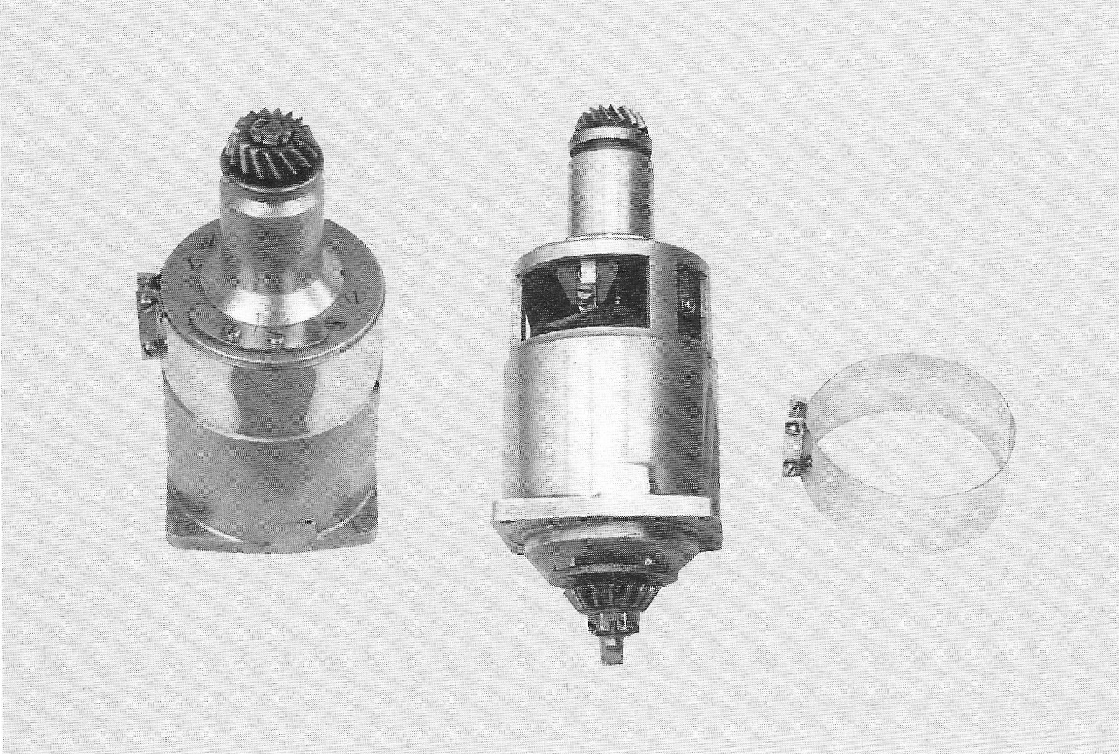
Dynamo, relay Dynamo The 1934 dynamo is of the third brush type, made by F&N.
The dynamo housing and support plate are made of aluminium. The
armature is 42,2 mm in diameter. The electrical mains is connected with the right main brush, which is the dynamo’s + brush. The left brush, the dynamo’s – brush, is connected to the frame by means of the contacts of the oil pressure switch. One lead of the field coil is connected with the + brush, the other one with the third brush. Without going into too much detail about the functioning of the dynamo, it is noted that the position of the third brush controls the number of magnetic field lines, flowing through the dynamo’s armature, and consequently the load current. The load current increases when the third brush is shifted towards the - brush and will decrease when the third brush is shifted towards the + brush. The dynamo’s neck is marked “4” and “1” for a load current of 4 or 1 amps respectively. The third brush dynamo is very different from the later model. The only common things are the top bearing, the nuts and keys and the retainer for the bottom bearing. Interestingly, the lamellas of the field coil in the third brush dynamo are exactly the same as those used in the very first NILFISK vacuum cleaner model S50. The maximum power of the dynamo is 25 – 30 Watt, which is totally insufficient for riding at night, even with the low power bulbs used in 1934. Control with the third brush works well in theory, but is impractical for daily use. F&N realised at an early stage that this system was inadequate, because early in the spring of 1934, a new dynamo with two brushes was being developed which included 56.
|
|
the new voltage and current back flow relay which was fitted on the Nimbus from number 1551 in April 1935. A rubber gasket between the neck of the dynamo and the camshaft housing is kept in place by an 11 mm wide tightening ring with a flat base. This ring is rather flimsy and was easily deformed when tightened. A higher and more robust design was introduced from number 2400.
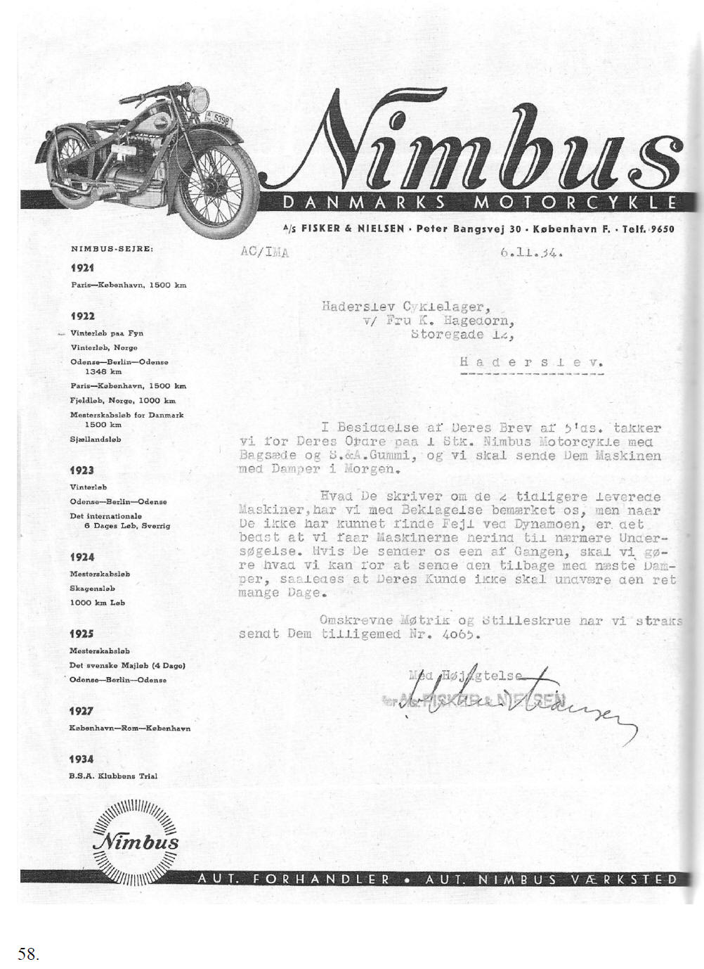
The third brush type Dynamo It can be concluded from the following letter, from F&N to K.Hagedorn in Haderslev, that there were problems with the electrical system. F&N did not want to acknowledge that because they were well into the development of a new dynamo.
57.
|
|
|
|
[Translation of page 58]
Nimbus The Danish motor cycle A/S Fisker & Nielsen · Peter Bangsvej 30 · Copenhagen F · Telephone 9650 AC/IMA 6.11.34
Motor Cycle Store Haderslev,
Referring to your letter of the 5th of this month, we want to thank you for your order for one Nimbus motorcycle with passenger seat with S&A rubber; we will send you the bike tomorrow by steam ship. We notice with regret what you write about the two machines which were supplied earlier, but because you were not able to find any fault in the dynamo, it is best that we get the machines over here for further investigation. If you send one at a time we will do what we can to return it by the next steamer so that your customer will not have to be without it for many days. We have sent you the referenced nut with adjustment screw immediately, as well as No 4065. Sincerely yours, A/S Fisker & Nielsen
[Nimbus logo] AUT. DEALER . AUT. NIMBUS WORKSHOP
58. [Right hand section]
|
|
NIMBUS SUCCESSES:
1921
1922
1923
1924
1925
1927
1934 NIMBUS Authorised Dealer · Authorised Nimbus Workshop. 58. [Left hand section] [End of translation of page 58] |
|
Oil pressure relay Because the electrical system is not equipped with an appropriate back flow relay, the battery can discharge through the dynamo when the dynamo voltage is lower than the battery voltage, especially if the engine isn’t running. To prevent discharge, the dynamo’s earth terminal is connected to the oil pressure relay which does not make contact with the frame until the oil pressure is high and the engine and the dynamo run at high revs. As mentioned earlier, the oil pressure relay and the lube oil pipe to the camshaft housing have been joined together. The system was primitive and unreliable, even for 1934. Various companies “Bosch” and “Lucas” amongst others had been applying combined voltage and current back flow relays for a number of years. 59.
|