|
Cylinder head, valves, kick starter, etc. Kick starter The kick starter system, which consists of a pedal, a spindle with torsion spring, a toothed sector, a pawl wheel and a spring loaded pawl disk has not changed from No 1301 until 9000.
The system has a tendency to slip, when the teeth of the pawl wheel
and pawl disk are worn. F&N has tested several tooth profiles over
the years, including pawl disks in various different forms and
thicknesses.
As early as August 1934, new drawings for the kick starter pedal arm
were made. The first model had a kick starter arm with a head of 33
mm and a bend of about 50 mm. The following model, which remained
unchanged during the remaining production period, had a head of
approximately 27 mm and a bend of 63,5 mm. Cover plate
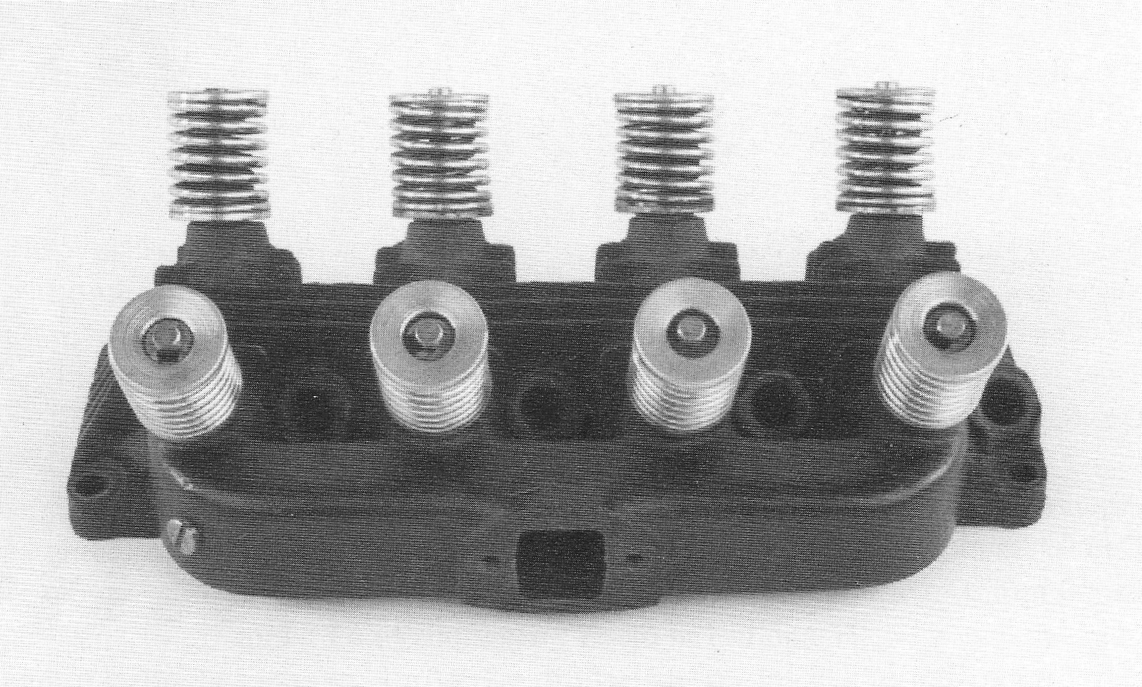
As mentioned before, the punched Cylinder head The 1934 cylinder head is, as with all later models, made of cast iron and is cast as one unit together with the inlet manifold. The combustion chamber is semi spherical. The valves are placed in valve guides, pressed into the head forming an angle of 60º with each other. The valve seats are at 45º.
43.
|
|
All cylinder heads below No 8500 have a flat base, designed for a copper-asbestos gasket and the inlet manifold also has a flat base.
1934-cylinder head. The screw on the left is a later modification, for checking with a vacuum meter.
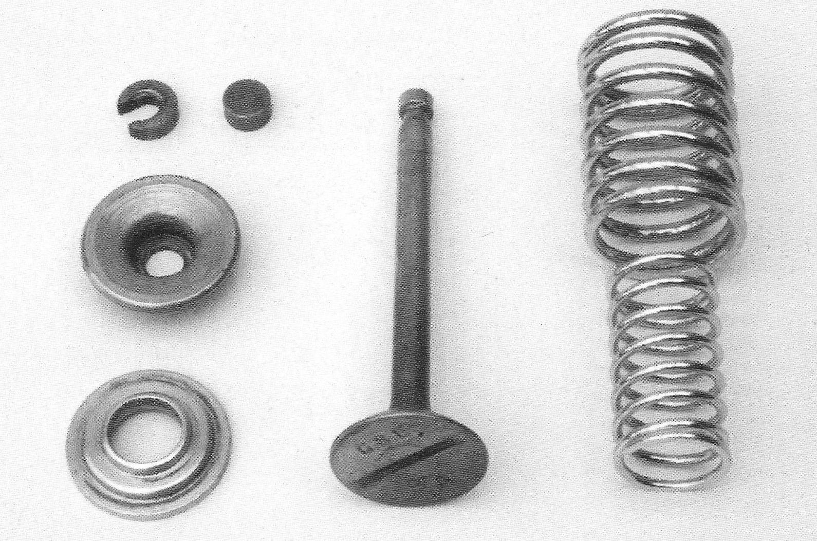
The 1934 cylinder head is distinguished from the later models by having a square suction hole. Valves The valves are from “A.Teves” Company. They are marked “GSE” and are designed for horseshoe shaped cotters.
The 1934 brochure describes the valves as having been fitted with
wearing caps, as shown by the assembly drawings, including special
adjustment bolts. It is impossible to determine however if engines
were actually supplied with these wearing caps on the valve stems.
It might have been a detail which was changed prior to taking the
machines into mass production.
44.
|
|
Part of an assembly drawing of the 1934 engine, please note that the valves are fitted with wearing caps. Valve guides Valve guides are made of cast iron and are basically the same for all models up to 13572.
Valve springs Two valve springs are used, which, at valve closure, exert a force of around 10 kg. The valve springs are nickel plated.
Spring cups The top spring cup is designed to be fitted with a horseshoe shaped cotter. The bottom spring cups are the same as with later models. Mica washers were not fitted below the bottom spring cup. The spring cups are nickel plated.
45. |
|
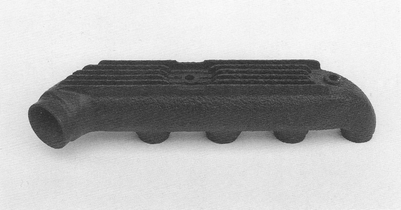
Valve with matching horseshoe shaped cotter, spring cups and springs. The wearing cups fit the valves and could be the type thought to be used. Exhaust manifold The exhaust manifold was unchanged from No 1301 until 2550. It is recognisable by the top and bottom cooling fins, which are uninterrupted along the entire length; the three middle ones are interrupted and form a circle around the attachment bolts. From No 2551 onwards, all cooling fins next to the attachment bolts have been cut off flush. The manifold is attached to the cylinder head with 8 mm bolts with a common head and special brass nuts with flanges.
46.
|
|
Exhaust manifold
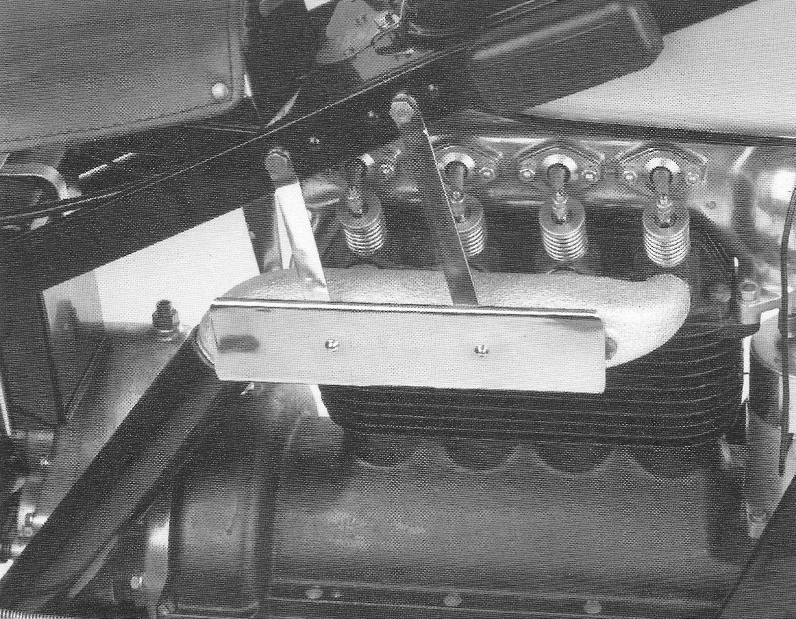
Heat shield for exhaust manifold
The first models built in 1934 were thought to have had no heat
shield for the exhaust manifold fitted, but a complaint from a motor
cycle reporter whose trousers caught fire, made F&N design and fit a
simple heat shield. From No 1550 onwards, the heat shield was modified to the familiar, more elegant type, made of chrome plated brass sheeting, which was used on all future models.
The new heat shield is, with the aid of two internal
reinforcements, fitted on the attachment bolts of the exhaust
manifold, which have been fitted with a 6 mm stud for that purpose.
To ensure that these reinforcements fit correctly around the bolts
or, perhaps to prevent rattling, it was necessary to grind away a
bit of the two outer cooling fins of the exhaust manifold. Whether
this was executed by F&N or by various mechanics, is unknown, but it
is rare to find a 1934 exhaust manifold without the ground cooling
fins.
47.
|
|
Exhaust manifold with heat shield.
|