|
Cylinder block, piston, crankshaft, flywheel, etc.
Cylinder block
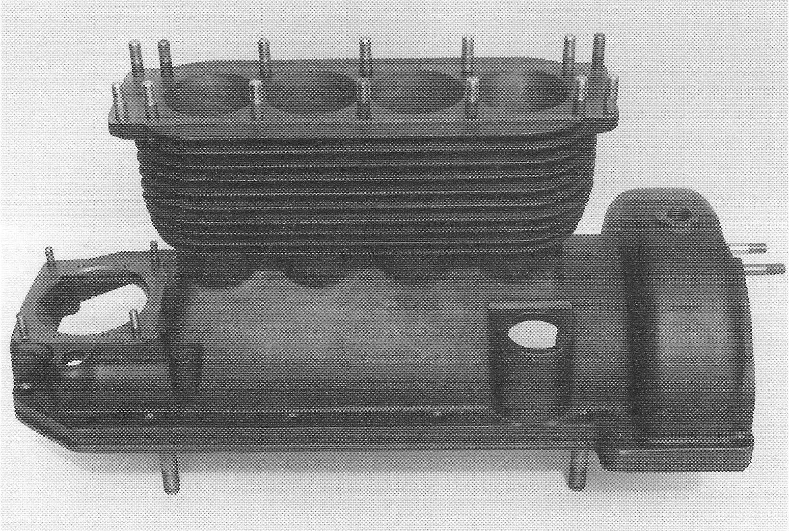
The cylinder block has been cast very roughly; flow lines can easily be seen in the metal as well as casting joints between the cylinders and the crank case. Vertical cooling fins cross the horizontal ones fore and aft. The engine number is stamped directly onto the flange of the crank case, which does not have the raised section of metal around the number which later models had. The area of the oil filling hole has been milled lengthwise, resulting in a straight edge.
Engine block, notice the rough casting.
The lube oil pipe to the gear box is fitted at the right side of the crank case, for which slots have been milled for the pipe to pass through.
21.
|
|
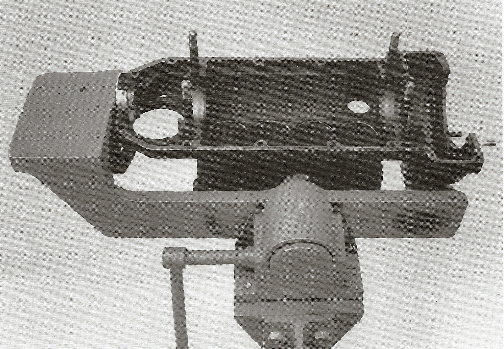
Engine block mounted in F&N’s original engine support; notice the milled slots for the lube oil pipe at the right side of the block.
The hole in the clutch housing is 18 mm and threaded, to which a threaded plug is fitted. This hole also serves to attach the block to the original F&N’s engine support, which is the reason that the thread was kept in place during the whole production period, even when the threaded plug was replaced by a cap in 1936.
PISTON
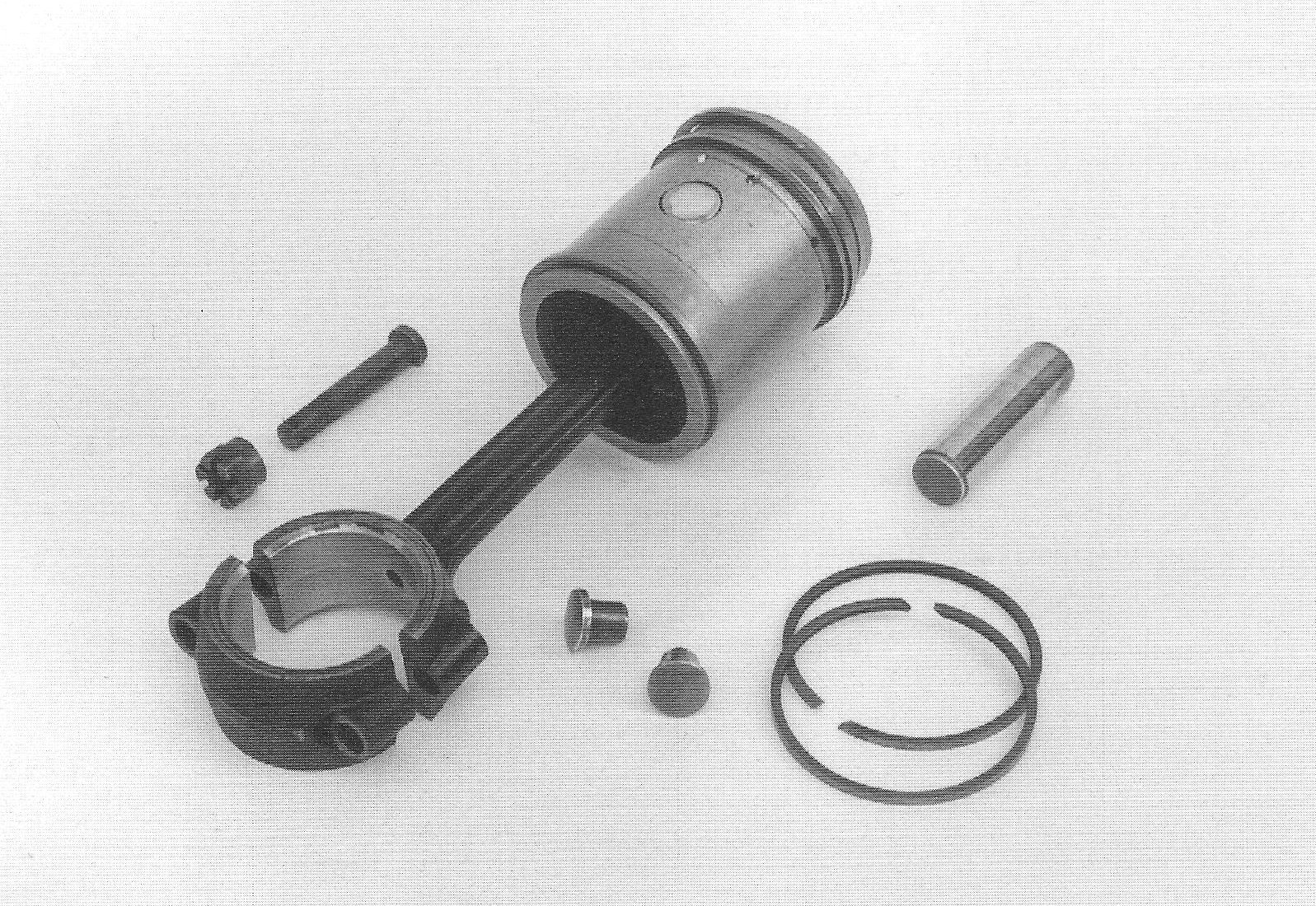
The pistons were purchased from “Kolben Schmidt, Hamburg”. They have a flat top and three piston rings near the top and one near the bottom. The rings, which are all 2,5 mm wide and have an angled gap, were supplied by a company called “A.Teves”. Gudgeon pins are of the floating type, with brass caps at both ends.
22.
|
|
Connecting rod, piston and gudgeon pin with brass end caps.
CONNECTING RODS
The connecting rods are drop forged and have a hollow shaft which serves as an oil duct for lubrication of the gudgeon pins and little end bearings. The big end bearing is made of white metal, without the later oil pockets at both sides. The little end bearing is made of bronze, with drilled holes at both sides for the lube oil, but without the later horizontal groove. The connecting rods are identified with numbers 1, 2, 3 and 4, corresponding with the cylinder numbers. To prevent commingling piston rods and their corresponding bottom bearing halves they are marked the same. The big end bolts are provided with split pin holes and castle nuts. The big end bearings have no shims.
CRANKSHAFT
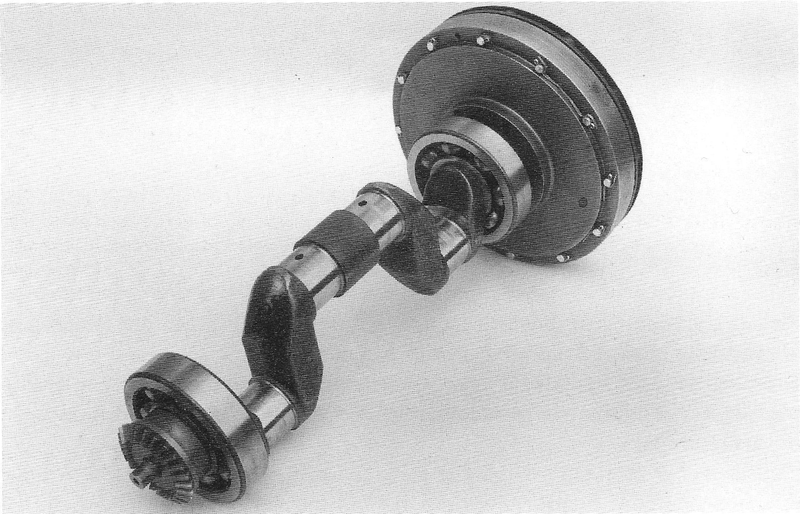
The 1934 crankshaft distinguishes itself from later ones through its oil ducts for pressure lubrication.
23.
|
|
The connection with the lube oil pump is by means of a spring loaded pipe fitted at the front side of the crankshaft. This pipe is directly connected to the lube oil pump, without any form of gasket, which is the case between it and the crankshaft, which also has no seal. Access to the oil ducts in the journals takes place by removing the three threaded plugs which are fitted at the end of the journals.
Main bearings are 2 pieces of 35 x100x25 mm deep groove ball bearings SKF No 6407, which is also used for later models. These days, it is often recommended to use a C2 bearing for the front main bearing, which reduces the axial movement of the crankshaft when declutching, which allows for a reduced clearance between the crankshaft and dynamo gear wheels.
1934 crankshaft; the lube oil pipe stubs and the bolts can be seen which give access to the oil ducts.
FLYWHEEL
The flywheel accommodates a built in clutch and the kick starter operating mechanism. The flywheel itself was basically unchanged from engine number 1301 until 8000. The flywheel is machined very roughly.
24.
|
|
|
|
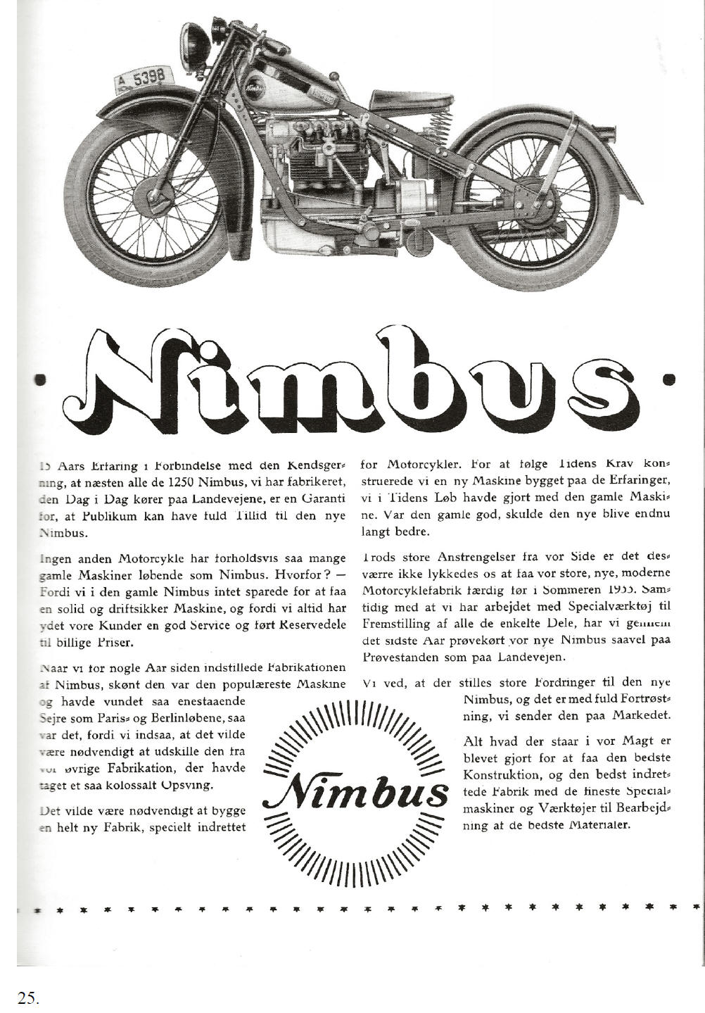
[Translation of page 25] ·Nimbus· 15 years of experience, together with the fact that almost all 1250 Nimbuses produced are still ridden on the highways, ensures that the public can have full confidence in the new Nimbus.
No other motorcycle brand has, relatively speaking, as many of the older machines in roadworthy condition as the Nimbus. The reason being is we have not compromised in the production of the previous model in producing a solid and reliable machine and because we have always given good service to the customers along with spare parts readily available at low prices.
When production of the popular Nimbus ceased a few years ago after winning races in Paris and Berlin, demand for motorcycles increased and it became apparent that production of future motorcycles would have to be segregated from the remainder of the Company’s products.
It was necessary to build a new factory specifically designed for motorcycle production. To meet current requirements and future expectations, a new motorcycle was built based on the experience gained from the earlier model. The earlier model was good, but the new model was even better.
Despite all efforts the construction of the new factory was not completed before the summer of 1933. During 1933, specialist equipment and tooling were used to produce all the parts and the prototypes were tested in the factory and on the roads. Demand for the new Nimbus is high and we are confident in launching it.
We endeavoured to develop and manufacture the finest motorcycles in a modern factory using the latest machinery, production processes and materials available.
25.
[End of translation of page 25]
|
|
|
|
[Translation of page 26]
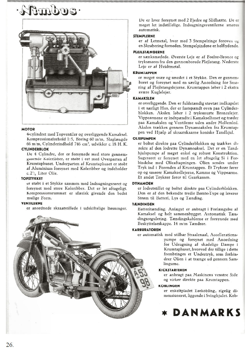
Engine 4-Cylinders with overhead valves and camshaft. Compression ratio 1:5. Bore 60 mm. Stroke 66 mm. Cubic capacity 746 cm³ Power output app. 18 hp. Cylinder block The 4 cylinders, have large, continuous cooling fins, and are cast in one piece with the upper part of the crank case. The bottom part of the crank case is made of cast aluminium, and also has cooling fins and an oil capacity of 2½ litres. Cylinder head is cast in one piece with the inlet manifold, and is provided with large cooling fins. It can be removed easily. The combustion chamber has a spherical shape, which is the optimum shape. Valves are positioned at an angle in exchangeable valve guides. They are provided with two valve springs and caps and can easily be adjusted. The inlet valves are lubricated automatically. Pistons are made of light metal with three compression rings at the upper end and one oil control ring at the lower end. The gudgeon pins are floating. Connecting rods are drop forged. The small end bearing is phosphor bronze and is lubricated under pressure through the hollow connecting rod. The big end is made of white metal. Crankshaft is very robust and is forged in one piece. It has drilled oil ducts and its special design allows for the lubrication of the connecting rods. The crank shaft runs in two substantial ball bearings. Camshaft is of the overhead type. It is fitted in a dust proof housing, which is attached on top the cylinder block. The shaft runs in two pressure lubricated bronze bearings. The rockers are placed in the camshaft housing and directly connect the cams with the valves, without the need of tappets. The camshaft is driven via the dynamo through the crank shaft, by means of bevel gears. Lube oil pump is bolted to the cylinder block and is driven directly by the vertical dynamo shaft. It is a gear pump having a very simple and robust design. The suction pipe has an easily detachable filter which is attached to the oil drain. Lube oil is pumped under pressure through the front end of the crank shaft. The oil is forced through the oil discharge pipe and lubricates the cam shaft bearings, cams and rockers. Another lube oil pipe discharges oil to the gearbox.
Dynamo is positioned vertically and is directly connected to the cylinder block. It is of the common ‘third brush type’ and feeds the battery, the lights and the ignition Ignition Battery ignition is fitted at the front end of the cam shaft as one unit and has an automatic ignition advance system. The spark plug leads have caps and the spark plugs are 14 mm. Carburettor is automatic with an adjustable jet needle and acceleration pump and is provided with an arrangement to extract hazardous fumes from the crank case which at the same time creates a negative pressure in the crankcase to prevent oil leakage. Kickstarter is mounted on the left side of the motorcycle and directly engages the crank shaft. Clutch is of the dry single plate type, with a robust construction and is placed in the fly wheel.
* DANMARKS MOTORCYKLE*
26.
[End of translation of page 26]
|
|
|
|
|
|
[Translation of page 27]
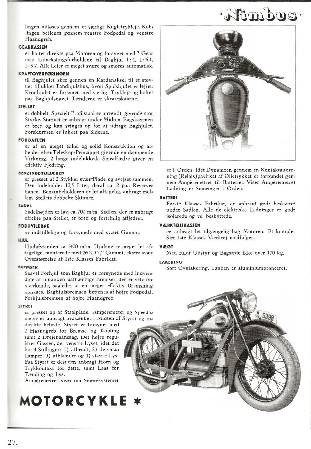
De-clutching is by means of a special (ball) thrust bearing. The clutch is operated by the left foot pedal and the left hand grip. Gearbox is directly attached to the engine, has three gears and, in conjunction with the rear wheel, has a reduction ratio of 1:4, 1:6,1, 1:9,7. All bearings are very robust and have automatic lubrication. Transmission to the rear wheel takes place through the shaft drive to the dust proof differential housing which contains the pinion gear with its bearing. The crown wheel is provided with a special thrust bearing which is attached to the rear wheel hub. The teeth are chamfered. Frame is double. A special type of profile steel has been used, which is extremely strong. The stand is placed in the centre. The rear mudguard is wide and can be hinged upwards to remove the rear wheel. The front mudguard is closed at both sides. Frontforks are of solid construction and also telescopic, which gives a damped spring action. Two long, enclosed coil springs provide effective suspension. Fuel tank is pressed out of two pieces of heavy steel plate, which have been welded together. The tank holds 12½ litres including a 2 litres reserve. The fuel tank is easily removed and is located between the two frame spars. Seat
The seat is positioned low, about
700 mm and the large, well sprung seat is attached directly to the
frame. Foot rests are adjustable and have heavy rubbers. Wheels The wheel base is 1400 mm. The wheels can easily be removed and are fitted with high quality, oversized, heavy duty 26” x 3½” tyres. Brakes Both front and rear wheels have enclosed, independently operated brakes, which are “self adjusting” so that a very effective operation is achieved. The rear brake is operated by the right foot pedal, the front brake by the right handlebar lever. Handlebars are made of pressed steel. The illuminated ammeter and speedometer are positioned in the middle of the handlebars. The handlebars are provided with two hand levers for brake and clutch and two twist grips. The right one controls the throttle, the left one the lighting which has four positions: 1) off, 2) parking lights, 3) low beam, 4) high beam. In addition the handlebar incorporates the horn and its operating button, as well as the ignition and lighting lock. The ammeter shows whether or not the lubrication system is working properly, because the dynamo charges the battery through the oil pressure operated relay and the ammeter. When the ammeter shows that the dynamo is charging the battery, then the lubricating system is working properly.
Battery of finest quality, well protected under the seat. All electrical wiring is well insulated and protected. Tool box is fitted at the bottom of the motorcycle and is easily accessible. A complete set of tools is included with the machine. Weight fully equipped including passenger seat less than 170 kg. Paint Black stove-enamelled, tank is aluminium coloured
27.
[End of translation of page 27]
|