|
Oil sump, lube oil pump, oil ducts, etc.
The lubrication system
The lubrication system of the 1934 model is distinguished from later models by having a fully pressurised lube oil system.
The oil sump, holds 2½ litres of oil. In the 1934 model F&N recommend oil with an S.A.E. 30 for winter use and S.A.E. 40 for summer use. The oil level is checked with the calibrated dipstick with 1 litre and 2½ litre marks.
The sounding rod or dipstick as it is called today is checked by hand and is of lower quality finish than on later models.
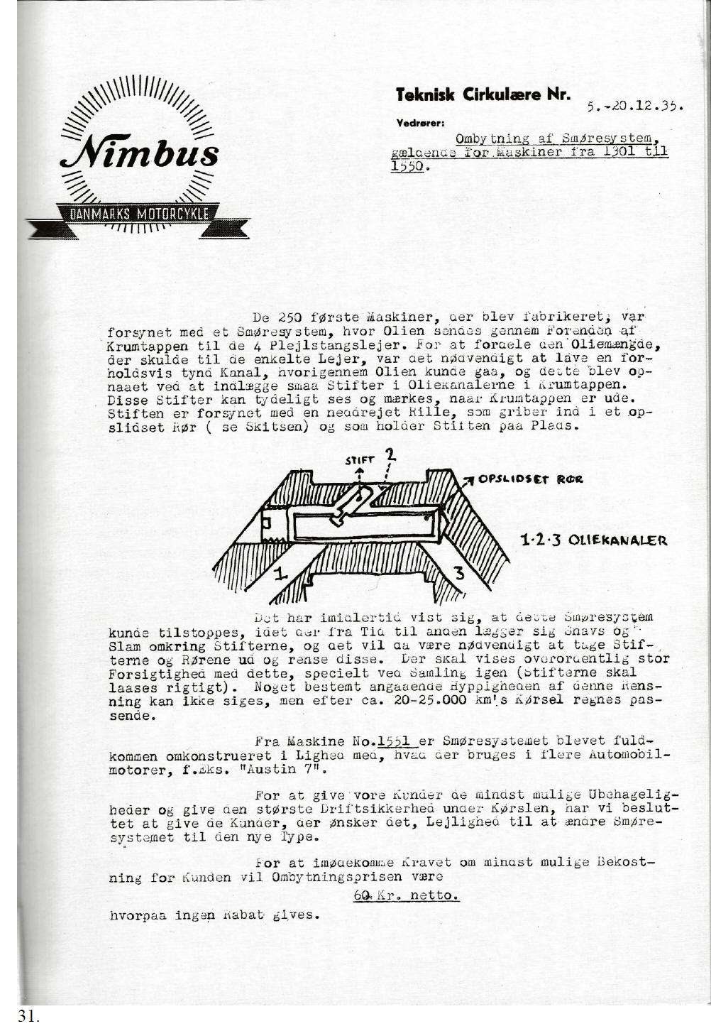
The dynamo driven lube oil pump, is a simple gear pump.
The oil pressure of 1.7 atm. Is achieved by a spring loaded pressure relief valve. The pressure relief valve is fitted directly at the front of the crank shaft, immediately behind the cover plate at the front of the crank case. The original purpose of the cover plate was to give access to the pressure relief valve without the need to totally disassemble the engine. There was a change of lube oil pump from number 1551, the position of the pressure relief valve was also changed but, as we know, the cover plate at the front of the engine remained on all later Nimbus motorcycles.
The bottom cover of the lube oil pump is fastened with four 5 mm x 13 mm bolts which have locking wire holes. The pump is mounted on the block with four 6 mm x 19 mm special bolts with a 6 mm high head.
The bottom cover of the lubricating oil pump is fastened with four 5 mm x 13 mm bolts, provided with holes to be secured with a piece of wire. The pump is mounted on the block with four 6 mm x 19 mm special bolts with a 6 mm high head.
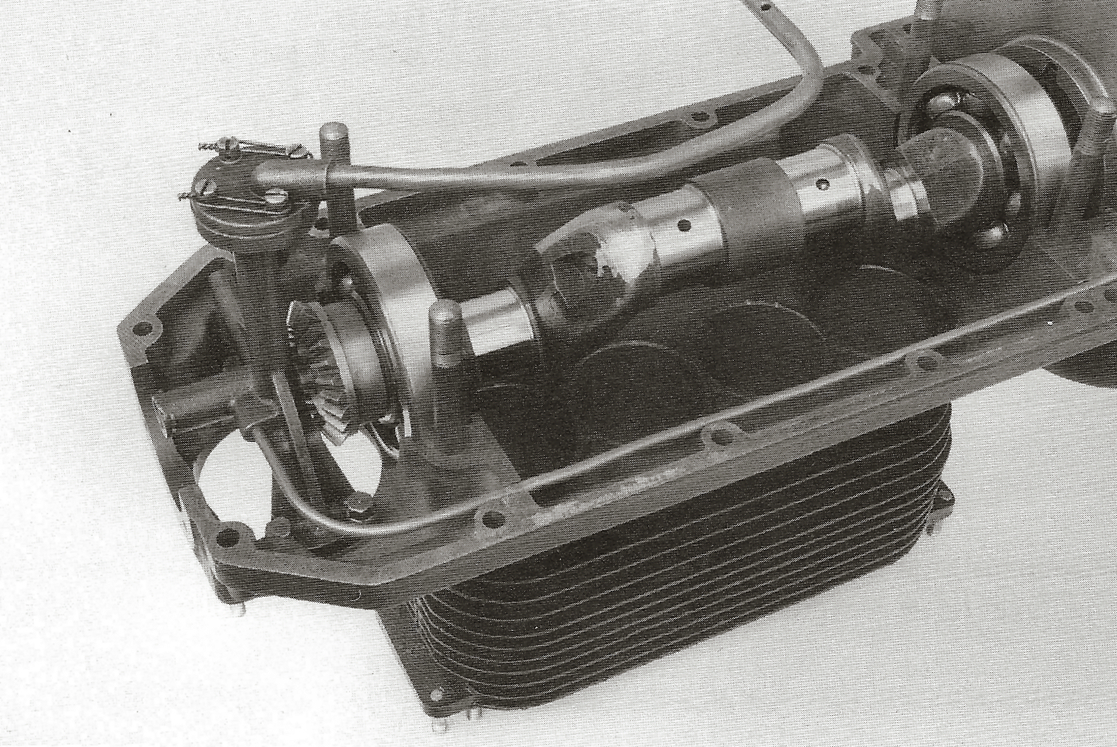
Lubrication of the crankshaft is through spring loaded pipe stubs at the front of the shaft whereby the pressure in the oil pipes forces oil to the individual big end journals.
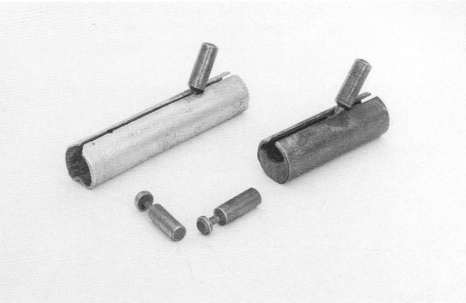
From here on, the oil is pumped through the hollow connecting rods to the piston pins. The volume of lube oil to the individual big end journals is controlled by small pins which are fitted in the mouth of the oil ducts.
The pins are retained in slit tubes, which are located in the big end journal’s oil duct.
The pressurised lube oil system caused many problems, amongst others choked oil ducts, leading to low oil pressure, causing excessive wear to the engines. Attempts were made to solve the problems by altering the pins in the slit tubes.
29.
|
|
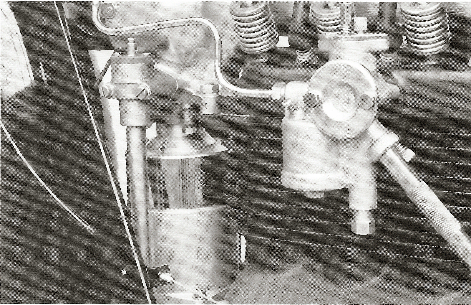
Lube oil pump with oil line
Initially the slit tubes were simple brass pipes. Later, probably around number 1350, two different types of slit tubes were used in the crank shaft. The slit tubes fitted in the two outer big end journals, were made of brass, with cast-in lead, which were bevelled at the bottom. Those in the middle two journals were slit tubes made of aluminium with a concave curve at the bottom. Both types of bevels, those of the brass slit tubes and those of the aluminium tubes with concave curve, improved oil flow. The lead in the brass tubes probably served the same purpose, because the heavy tubes were, as a result of the rotating crank shaft, pushed to the opposite side of the oil duct, leading to more space under the tubes. The application of aluminium tubes to the inner big end journals and the reason why the split tubes were different, remains unclear.
In conjunction with the alterations of the slit tubes, the pins were also changed. The first pins were of a simple construction, later they had a more rounded and bevelled shape, probably to reduce the risk of breaking, due to cracking.
We have seen a lot of 1934 crank shafts with badly worn aluminium tubes. We also encountered several broken pipes, so the quality of the system was questionable.
30.
|
|
|
|
[Translation of page 31]
·Nimbus· Technical bulletin No 5.-20.12.35. Danish motorcycles Subject: Modification of the lube oil system, applicable to machines No 1301 until 1550.
The first series of produced machines were fitted with a lube oil system which allowed lube oil to flow from the front end of the crank shaft to the four big end bearings. In order to distribute the oil to the individual bearings, it was necessary to incorporate a relatively narrow oil duct which allowed the oil to flow through and this was achieved by fitting small pipes in the oil ducts of the crank shaft. These pipes can easily be seen and felt when the crank shaft has been removed. Each small pipe incorporates a groove which points downward and which slides through a slot tube (see drawing) and holds the small pipe in place.
[Drawing] 1, small pipe, 2, slit tube, 1.2.3. oil ducts, 3.
The lube oil system, was however, susceptible to choking. From time to time contamination and sludge collects around the pipes which necessitate removing the pipes and slit tubes for cleaning. When doing this, the utmost care has to be taken, especially when reassembling these parts (the small pipes need to be locked in correctly). We cannot comment about the frequency of this cleaning, but it would be prudent to do this after 20-25,000 km (12,500 – 15,500 miles)
From machine number 2551 onwards, the lube oil system has been fully modified, comparable to what is used in many automobile engines e.g. the “Austin 7”.
To give our customers the least possible inconvenience and also increased reliability, we have decided to offer the option to have the lubricating system converted to the new system.
In order to meet this requirement at minimum cost, the price to customers for converting has been set at 60 Cr. Net on which no discount will be given.
31.
[End of translation of page 31]
|
|
|
|
[Translation of page 32]
·Nimbus· Technical bulletin No 5.-20.12.35. Danish motorcycles II. Subject: Modification of the lube oil system, applicable to machines No 1301 – 1550
The engine will be provided with a new crank shaft, a new lube oil pump housing, new lube oil piping and will be assembled with the existing big end bearings.
Because the engine has to be dismantled entirely, we advise our customers to have a new sprung clutch installed at the same time to allow smoother running and gear changes without the sharp clunk when changing to third gear.
In addition, the gear claws have to withstand less stress, so they will last longer. The sprung clutch costs 8 Cr. net without discount, but only when installed during the engine strip down to have the oil system changed.
In the interests of Customer satisfaction, we ask the Retailers to inform the owners of machines with serial numbers 1301 through 1550, about the above conditions and advise them to have those modification carried out.
Every order will be carried out immediately, but the factory has to be given 8 days notice.
32.
[End of translation of page 32]
|
|
Pins with slit tubes
The lube oil pump also supplies oil to the camshaft housing as well as to the gear box.
It is remarkable that the lube oil pipe to the gear box is connected to the outlet of the oil pressure relief valve of the lube oil pump. By doing this, the gearbox doesn’t get oil until the relief valve opens. This means, that when the lube oil pressure is low, e.g. resulting from worn bearings or a worn oil pump, the pressure relief valve will not lift and the gear box will not be lubricated. This problem is clearly evident in the number of 1934 gearboxes that survive and those that have survived show symptoms of overheating, i.e. blue discolouration and friction marks in the gear box shaft.
The cam shaft bearing bushes are lubricated under pressure, as with later models. The lube oil of the rear camshaft bearing flows back over the bottom of the camshaft housing where small elevations form cups in the casting, resulting in splash lubrication for cams and rockers. The lube oil flows back through a return pipe to the crank case which also contains the pressurised lube oil supply line.
Relative to the lube oil system of 1934 is the oil pressure operated relay in the lube oil line to the camshaft housing. The oil pressure control relay is connected by a lead to the dynamo and
33.
|
|
forms the connection between frame and dynamo when the oil pressure is high enough, or, more correctly, it serves as a current return relay by disconnecting the dynamo from the frame, when the engine stops and the oil pressure drops.
Lube oil pressure relay
The lube oil pressure relay is by far the rarest Nimbus part. As far as I know, not a single one has survived. Vagn Gjerlang however has made a few magnificent copies, partly based upon photographs, and partly based upon a relay on the merry-go-round Nimbus from Copenhagen (60% scale models).
F&N quickly became aware of the problems with the lube oil pressure system and from engine No 1551 onwards the lube oil splash system was employed, where oil is sprayed through two nozzles against the revolving crank shaft where it is collected in oil cups from where it flows through short ducts to the big end bearings. This reliable and robust system was, as we know, applied to all later engines.
Nimbus owners with the old lube oil system were offered the option to have it converted into the new system at a moderate cost. Conversion consisted of fitting a new lube oil pump housing, a new lube oil pipe with nozzles and a new crank shaft with lube oil cups.
34.
|
|
The new lube oil pipe was fitted on the left side, which required new slots to be milled for fitting the oil pipe. The old slots at the right side were isolated from the clutch housing with a plug.
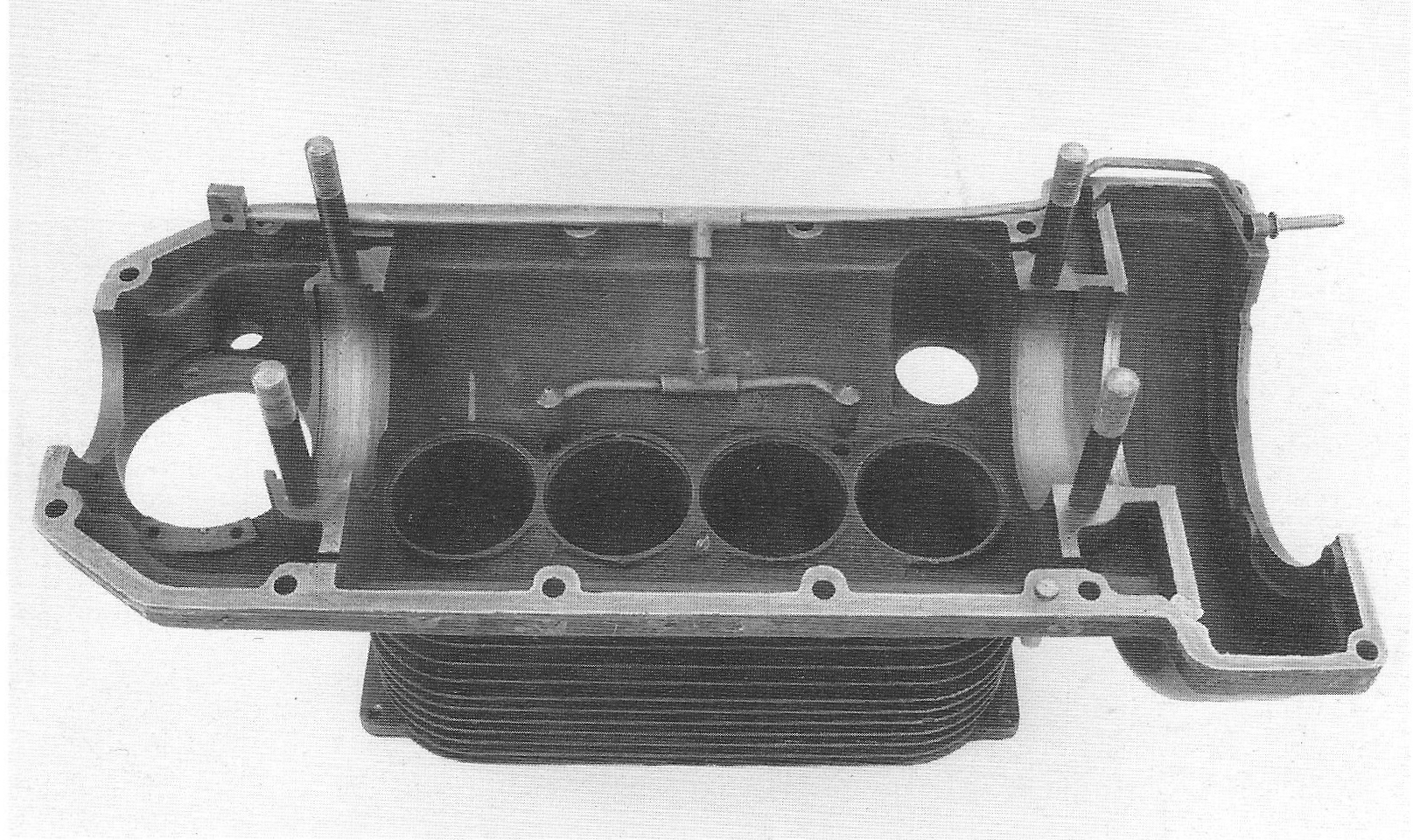
1934 engine block, modified with the new lube oil splash system
For guiding the modified lube oil nozzles, two holes were drilled in the engine block. These holes were placed quite deep, which required extra long nozzles. The engine blocks which were designed for the lube oil splash system had a small elevation in the cast material in which the guiding holes for the lube oil nozzles were drilled resulting in shorter splash nozzles
Crank case
The earliest crank cases are easily recognised by the small ridge which, from No 1301 – 2400, is fitted at the inner side of the sump base to support the suction line of the lube oil pump.
In the 1934 crank case, ridges have been applied at the right side near bolt holes No 2 and 5, for attaching the lubricating oil pipe. From engine No 1551 onwards, the lube oil pipe
35.
|
|
was fitted on the left side, so this side of the crank case was also provided with ridges. The ridges on the right side remained on all later crank cases. Externally, the 1934 crank case can be recognised by its four “legs” at the bottom and also by the very clear slots for the bolts of the unpolished crank case.
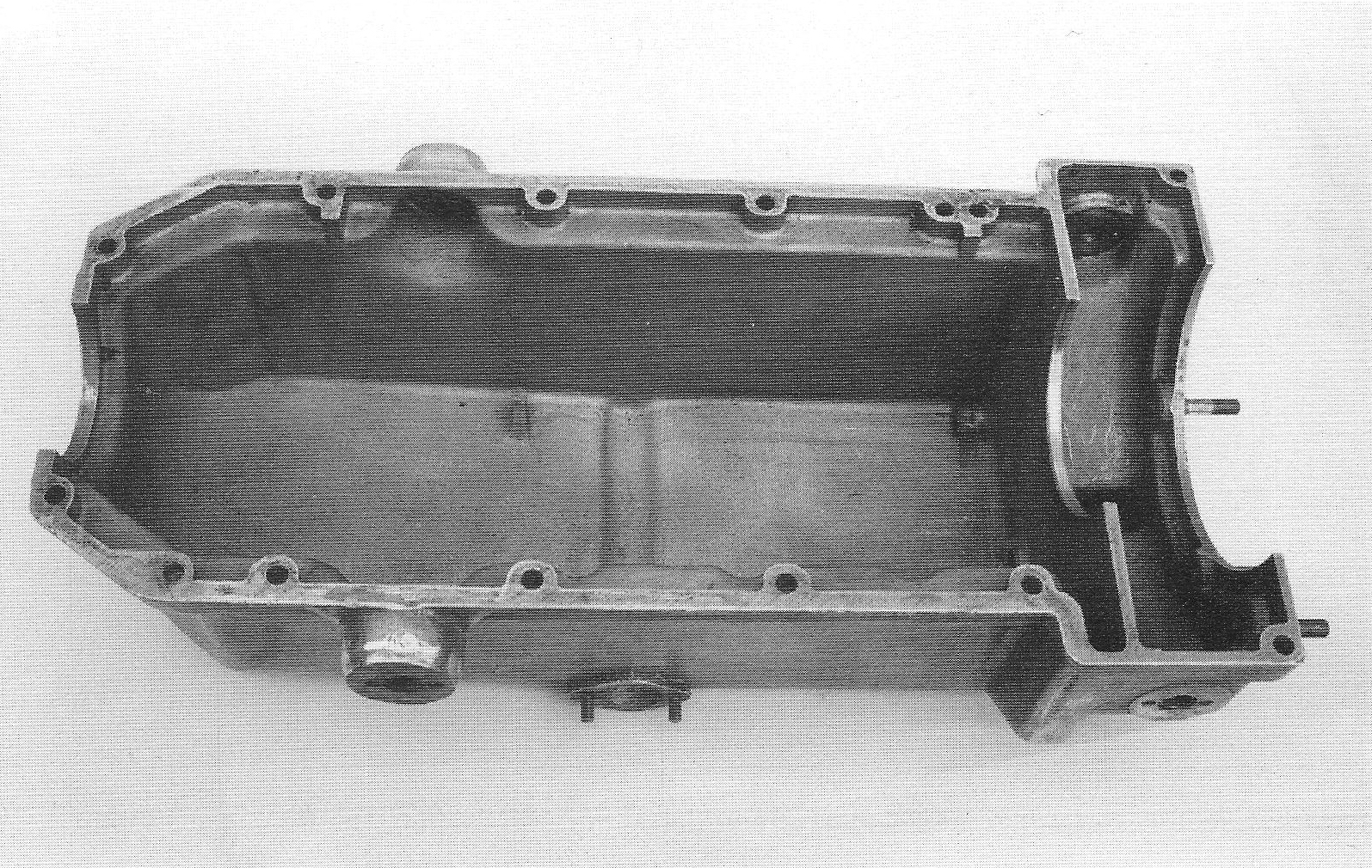
Crank case; please note the elevation on the bottom and the ridges for the lube oil pipe on the right hand side.
From No 1400 onwards the crank case was strengthened with a 60 mm long rib section at the base between the cooling fins directly under the kick start shaft.
The drain hole of the flywheel housing is positioned further to the rear than with later models. This causes the centre stand to close off the hole when it is folded back, leading to a poor aeration of the flywheel housing. In many 1934 crank cases an additional hole was drilled later in order to improve aeration of the flywheel housing.
When the 1934 engines were converted to the new lube oil system, it was necessary to remove some material from the inner side of the left flange, to create room for the new lube oil pump. These slots can often be seen on 1934 crank cases. Some millings have been done very professionally, possibly by F&N.
36.
|
|
Others, however look like the material has been beaten out roughly by the local blacksmith.
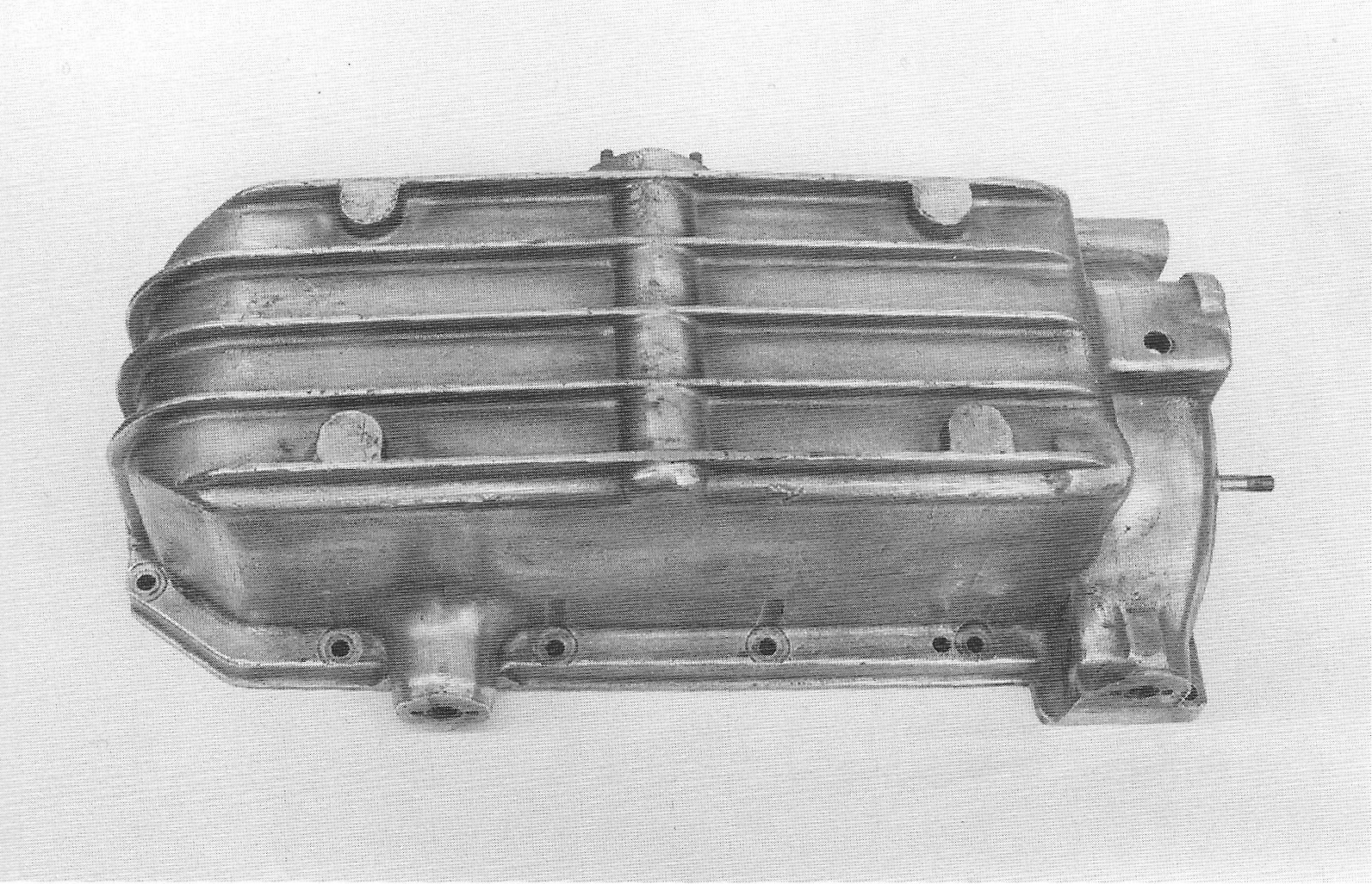
Crankcase; please note the missing strengthening near the kick starter shaft. Wear marks, caused by the centre stand can be seen next to the drain hole of the flywheel housing.
Crankcase bolts
The bolts for holding the crank case and the block together are 8 mm. These bolts have a flat, fully countersunk head with a narrow groove. Possibly from No 1451 onwards, the bolts were provided with a slightly spherical head. The heads appeared to be too weak, often resulting in the groove being squeezed when the bolts were tightened. From No 7501 onwards, the heads were made higher, more spherical and with a wider groove. The nuts of the crankcase bolts have a 14 mm head, which is applicable to all Nimbus 8 mm bolts.
37.
|
|
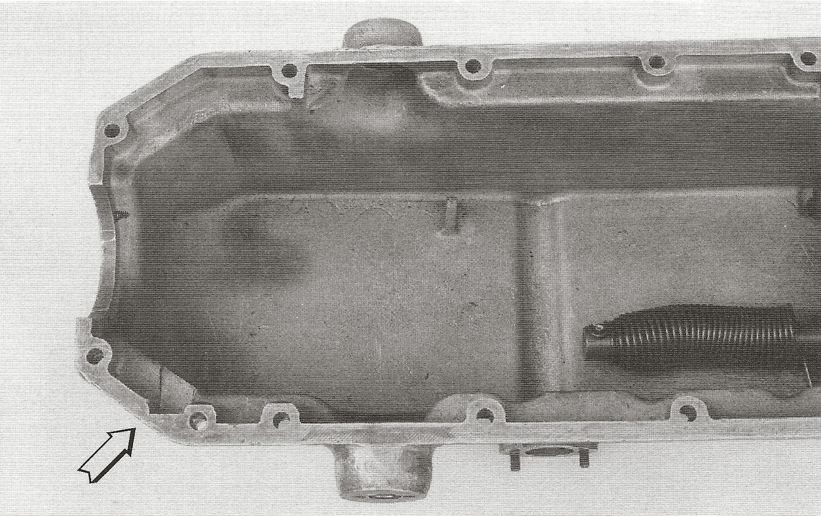
1934 crank case with a milled slot at the side to locate the 1935 lube oil pump.
Lubricating oil filter
The lube oil filter is, as with all Nimbuses built thereafter, a plain gauze filter, soldered on a brass cover. The covers of the early filters have a roughly cast outside. The covers were most probably nickel plated.
38.
|