|
Carburettor, oil supply, etc.
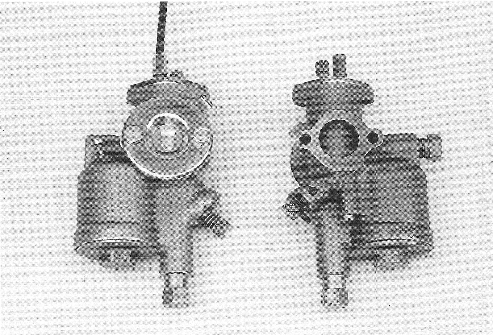
Carburettor The carburettor has been designed by F&N, which was very unusual. The majority of motor cycle manufacturers at that time bought carburettors from specialist companies.
The carburettor housing is cast in red
brass and is matt nickel plated.
The fuel supply is controlled by a
float and a conical valve. The float housing is equipped with a
‘tipper’. When the engine is cold the intake air is controlled by
turning a choke plate downwards at the front of the intake opening.
The air mixture for idle speed is controlled by a finger screw at
the back of the carburettor housing.
59.
|
| The top cover is made of chrome plated iron. The earliest models had their covers attached by means of cheese-head screws, later models had countersunk screws. The carburettor did not have an air filter as such, but had a chrome plated brass cover plate fitted at the front of the intake. This cover plate has a small bent lip, which presses the throttle plate against the carburettor housing.
It was difficult to adjust the idle and
low speed with the 1934 carburettor, consequently, starting from
around 2488, the bores for the idle mixture were modified.
1934 carburettor Type 1. Because these changes led to a significant improvement at low revs, many of the old carburettors were modified. A modified 1934 carburettor can be
60.
|
| recognised externally by the bore for the idle speed at the front of the throttle valve, which is about 2 mm in diameter, whereas with an original ”2” carburettor, it has a diameter of around 0,5 mm, while there is no bevelled edge for the securing spring around the threaded hole of the adjustment screw for the throttle valve. Fuel pipe The 1934 fuel pipe is a nickel plated 6 mm copper pipe with two right angles. The pipe is very stiff and it therefore transmits the engine’s vibrations to the fuel tank leading to cracks and leakage. In order to dampen these vibrations, starting with number 1551, a loop has been formed in the fuel pipe. Lube oil return pipe The combined lube oil pressure and return pipe between the lube oil pump and camshaft housing is basically of the same construction as on later models but is, as mentioned before, combined with the oil pressure relay.
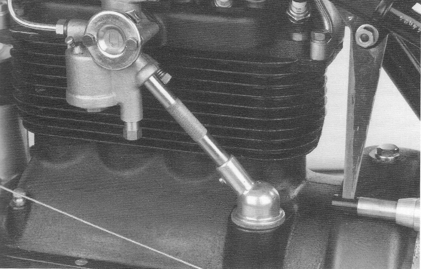
Crank case ventilation pipe.
61.
|
|
Crank case ventilation The crank case ventilation pipe, which connects the crank case with the carburettor, serves to create a slight vacuum in the crank case, allowing hazardous fumes to be removed and oil leakage to be reduced. Simultaneously, oil fumes are added to the inlet air, which lubricates the inlet valves.
The head of the crank case ventilation
pipe, which serves as an oil separator, has a full cylindrical neck
and forms a somewhat smaller angle as compared to later models. The
pipe itself is around 126 mm long and has a cross pattern of about
40 mm long, approximately 50 mm from the bottom.
62.
|