|
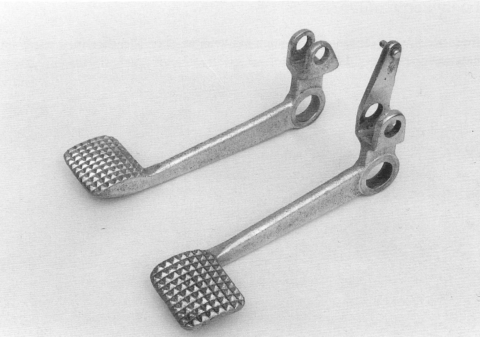
Fuel tank, Pedals, Gear lever, etc. Footrests The 1934 footrests resemble the later foot rests, but have round heads. Because of these round heads, the footrest rubbers can rotate around the pegs. This problem was solved by the end of 1935, by making the ends of the pegs and the bottom of the hole in the rubbers square. Foot rests, made for the Nimbus, which are square over the whole length, can be found. I don’t think they are original, but are an OEM (Other Equipment Manufacturer) product, specially produced to solve the problem with the rotating footrest rubbers. 76.
|
| Foot rest rubbers Round footrest rubbers without special characteristics. Probably with a round inner hole.
Footrests and footrest rubber, in front the ‘square’ OEM product.
Brake
The brake pedal, fitted on the right
footrest, is bent somewhat outward and is shorter than with later
models. It does not have a hole for the brake rod for a sidecar.
The clutch can be operated through
either the clutch pedal, mounted on the left footrest, or with the
hand lever on the left hand side of the handle bars. In principle,
the clutch pedal is made as a mirror image of the brake pedal, but
with a vertical lever for the clutch cable.
77.
|
|
Brake- and clutch pedal
The pedals are fitted on a shoulder on
the pegs of the footrests. In order to keep distance and prevent
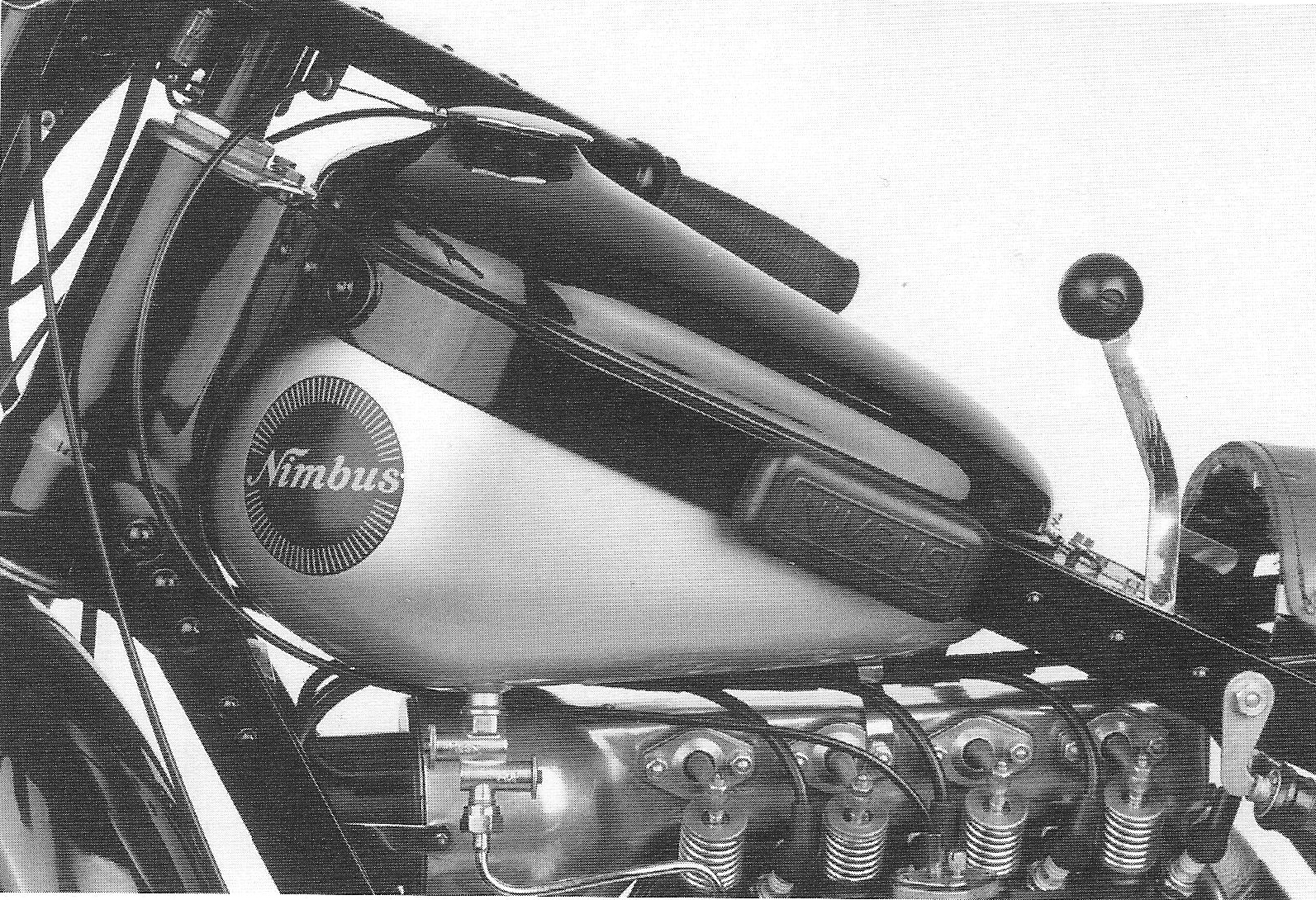
wear, a washer is fitted as a spacer between pedal and frame. Fuel tank
The fuel tank has a flat base with the
petrol tap fitted at the front base of the tank. The tank logo is a round, black transfer with a diameter of 86 mm with the name Nimbus and a golden halo. There is no rubber spacer between tank and frame. The petrol cap is chrome plated and has a 3 mm high edge.
78.
|
| Petrol tap The petrol tap on the first 1934 models is a rotating tap with reserve and filter. The make is unknown. During 1934 a double push tap manufactured by “Zöblitz” was fitted.
Tank and petrol tap
Hand Gear Lever All 1934 models have a hand gear lever The gear lever, which is guided by the gearbox lock and by slots in the frame plate, has 4 positions: 1st gear, neutral, 2nd gear and 3rd gear. From No 1526 on, five notches were made in the gear lever gate, creating an additional neutral position between 2nd and 3rd gears. This is especially practical when gearing down using double clutching and blipping the throttle; which is necessary to prevent excessive “tooth brushing”.
79.
|
|
|
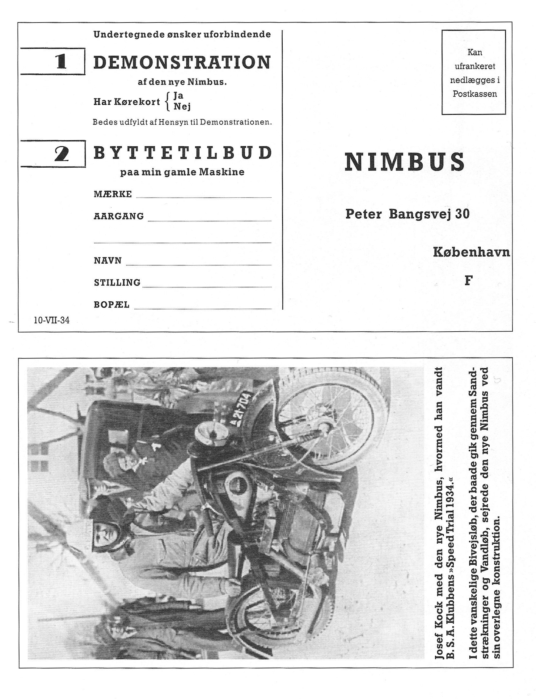
| [Translation of page 80] [Left hand section] The undersigned requests without commitment 1 DEMONSTRATION of the new Nimbus. Do you have a driver’s licence {Yes, No For a demonstration, please fill this out 2 TRADE-IN OFFER for my old machine MAKE __________________________________________ YEAR____________________________________ ________________________________________________ NAME__________________________________________ PROFESSION________________________________________ ADDRESS__________________________________________
10-VII-34
[Right hand section] No stamp necessary.
NIMBUS Peter Bangsvej 30
Copenhagen
[Photograph] Josef Koch with his new Nimbus, on which he won the “1934 Speed Trial” of the B.S.A. club. During this demanding race over secondary roads, stretches of sand and through water, the new Nimbus, with its superior construction, triumphed.
80.
[End of translation of page 80]
|
|
|
|
[Translation of page 81] Guidelines for using the MOTORCYCLE
[Nimbus logo]
Model 1934
A/S Fisker & Nielsen. Copenhagen F. Teleph. 9650
81.
[End of translation of page 81]
|
|
|
|
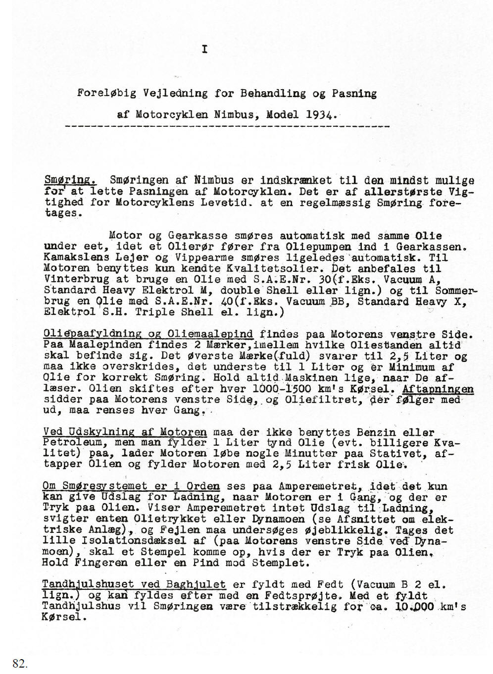
[Translation of page 82] Temporary manual for the use and maintenance of the 1934 Nimbus Motorcycle, Model C. Lubrication. The lubrication system on the Nimbus is not complicated and it is of the utmost importance for the life of the motorcycle that regular lubrication takes place. The engine and the gearbox are automatically lubricated with the same oil, via a lube oil pipe which runs from the lube oil pump to the gear box. The bearings of the camshaft and the rockers are automatically lubricated the same way. Only quality oils may be used for the engine. For winter use S.A.E. 30 oil, e.g. Vacuum A, Standard Heavy Elektrol M, double Shell or similar is recommended and for summer use S.A.E. 40 oil, e.g. Vacuum BB, Standard heavy X, Elektrol S.H., Triple Shell or similar.
The lube oil filler and dipstick
are located on the lefthand side of the engine. When rinsing the engine, no petrol or solvent may be used; fill the engine up with 1 litre of thin oil (a lower quality may be used), run it on the centre stand for a couple of minutes, drain the oil and fill the engine up with 2.5 litres of fresh oil. To check that the lube oil system is in good order, check that the ammeter shows a reading when loading takes place with the engine running and there is, presumably, oil pressure. If the ammeter does not show any reading indicating loading of the engine then either the oil pressure is low or zero or the dynamo has failed (see the paragraph on the electrical installation) and the fault has to be investigated immediately. If the small insulated cap (at the left side of the engine, near the dynamo) is removed, the plunger will pop up if there is oil pressure; hold the plunger with the finger or a small stick. The gearwheel housing of the rear wheel is filled with grease using a grease gun (Vacuum B 2 or similar). A gearwheel housing filled with grease is sufficient for about 10,000 kilometres.
82. [End of translation of page 82]
|
|
|
|
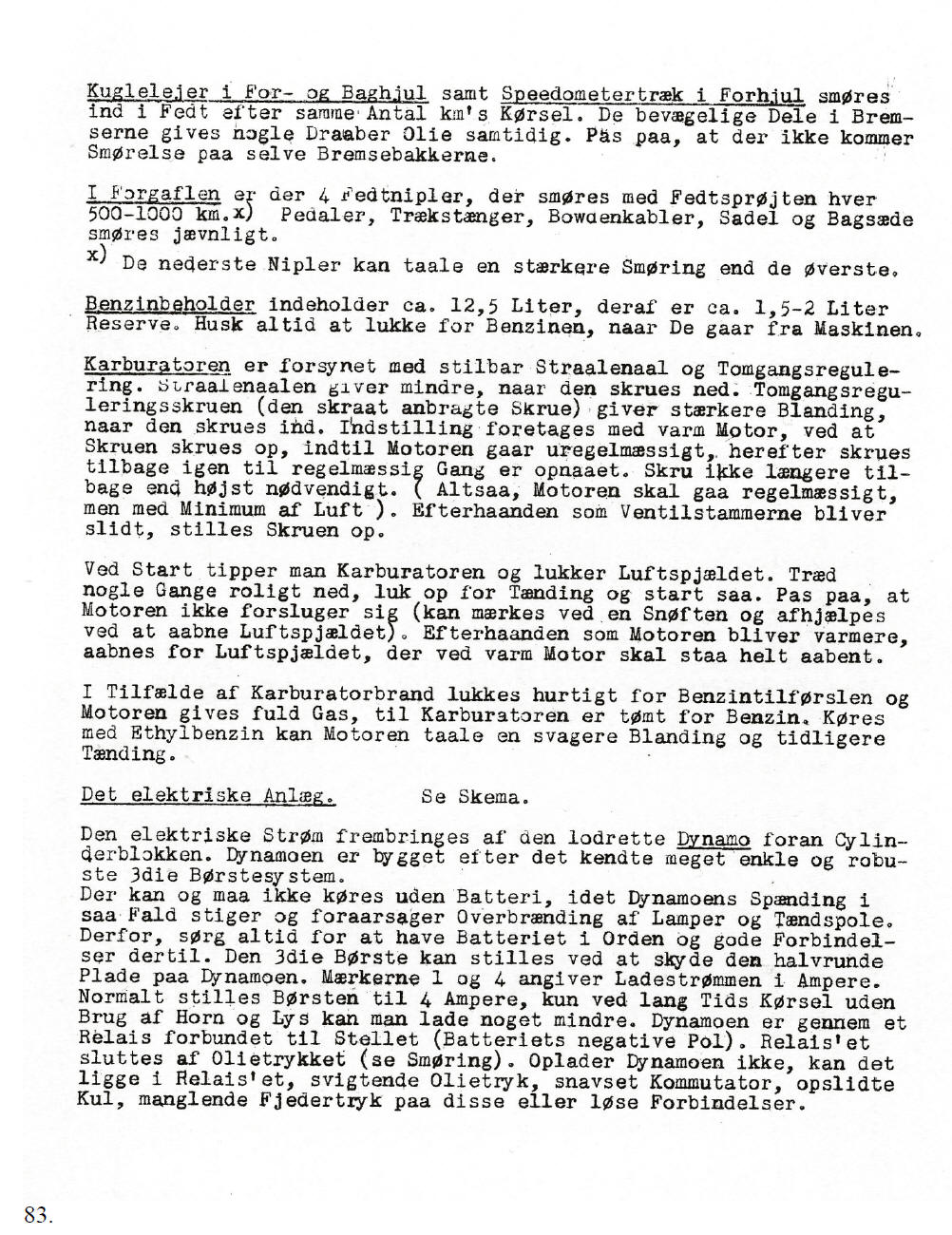
[Translation of page 83] The ball bearings of the front and rear wheels and the speedometer drive at the front wheel are lubricated with grease after the same number of kilometres. Simultaneously, the movable parts of the brakes can be oiled. Take care not to contaminate the brake shoes with oil.
On the front fork, 4 grease
nipples are fitted, which need to be lubricated every 500 – 1000
km. Pedals, pull rods, Bowden cables, seats and passenger seat
should be lubricated regularly. The fuel tank contains 12.5 litres, of which about 1.5 – 2 litres is the reserve. Please remember to shut off the petrol supply when getting off the motorcycle. The carburettor has an adjustable jet needle and an adjustment for the idle speed. The needle gives less petrol when it is screwed down. The set screw for the idle speed (the one placed at an angle) gives a richer blend when screwed in. The adjustment takes place with a warm engine by screwing the set screw for the needle up until the engine starts to run erratically, after which it is screwed back until the engine runs smooth again. Do not screw the set screw back more than absolutely necessary. (The engine runs smoothly with a minimum of air). If the valve stems wear over time, the set screw has to be adjusted again. To start the engine, allow the carburettor to overflow and close the choke valve. Depress the kick starter calmly down a few times, then switch the ignition on and start the engine. Take care that the engine does not choke (in which case you will hear a sniffing sound, which can be corrected by opening the choke valve). Later, when the engine gets warmer, the choke valve, which has to be fully open when the engine is hot, is opened. If the carburettor catches fire, the fuel supply to the engine has to be shut off quickly and full throttle given until the carburettor contains no more petrol. When using ethyl petrol, the engine is able to tolerate a poorer blend and an earlier ignition. The electrical installation (see schematic)
The electrical power is generated by the
vertically placed dynamo, at the front of the engine. 83.
[End of translation of page 83]
|
|
|
|
[Translation of page 84]
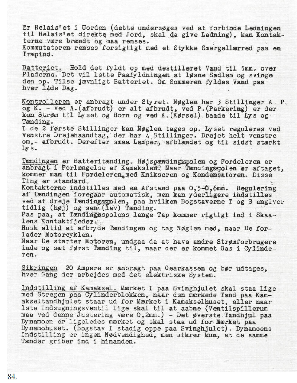
Check if the relay is working correctly
by connecting the wire running to the relay directly to earth
causing charging again. The battery. Keep it topped up with distilled water to 5 mm above the plates. This can be done by loosening the seat and tilting it forward. Check the battery at regular intervals. In summer, distilled water has to be added every fortnight. The ignition switch is located under the handle bars. The ignition key has three positions, A, P and K. – In position A (Afbrudt = off) everything is off, at P (Parkering = parking) there is only power available for lights and horn and at K (Kørsel = operating) there is power for both lights and ignition. In the first two positions the key can be taken out. The lights are operated with the left hand twist grip, which has four positions. Turning it fully to the left, - the lights are off, then parking lights, low beam and finally high beam.
The Ignition
is a battery ignition. The ignition coil and distributor are placed
in line with the camshaft. A 20 amp fuse is located on the gear box and must always be removed when working on the electrical system. Positioning of the camshaft.
The mark
I
on the flywheel has to align
with the mark on the cylinder block when the marked tooth of the
camshaft gearwheel lines up with the mark on the camshaft housing or
when the inlet valve of the first cylinder is just opening (the
valve clearance in this position must be 0.2 mm). – The upper
gearwheel is also marked and must be lined up to the mark on the
dynamo housing (the character
I
is still on top of the flywheel).
84. [End of translation of page 84]
|
|
|
| [Translation of page 85] IV
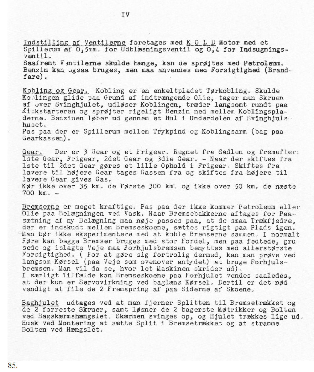
The valves
must be adjusted with a COLD
engine with a clearance of 0.5 mm for the exhaust valves and 0.4 mm
for the inlet valves.
Clutch and gear.
The clutch is a single plate clutch. If the clutch starts slipping
as a result of oil contamination, remove the plug on top of the
flywheel, declutch, rotate the engine slowly with the kick starter
and spray petrol liberally between the clutch plates. The petrol
will run out at the bottom of the flywheel housing.
The gears.
There are three gears and a neutral position. Counted from the seat
forward: 1st gear, neutral, 2nd gear, 3rd
gear.
The brakes
are very powerful. Take care not to spill solvent or oil on the
brake linings when washing the bike. When the brake shoes are
removed for fitting new linings, care has to be taken that the small
pull springs, fitted between the brake shoes, return to their
original positions. (If necessary mark them before dismantling) Do
not experiment with connecting both brakes together.
85.
[End of translation of page 85]
|
|
|
|
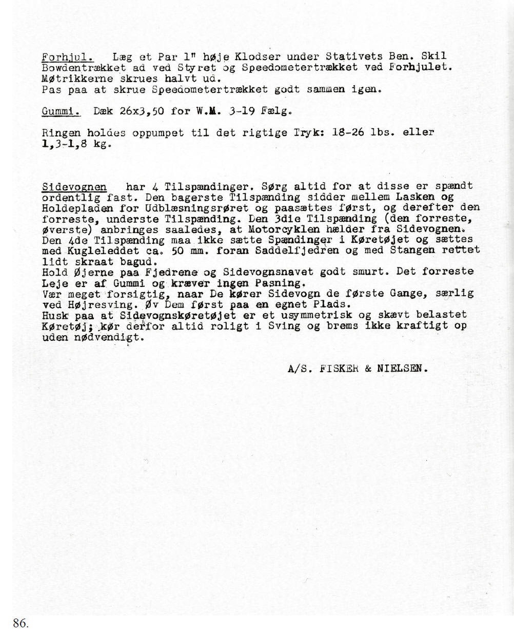
[Translation of page 86]
Front Wheel.
Place a couple of 1” high wooden blocks under the centre stand legs.
Remove the Bowden cable from the handle bars and from the
speedometer drive at the front wheel.
Tyres.
26 x 3.50 for W.M. 3-19 rim. The sidecar has four fastening rods.
Ensure they are always secured tightly.
The rear fastening rod is positioned between the frame strap and the
attachment plate for the exhaust pipe and has to be tightened first
and thereafter the front, lower rod. The third fastening rod (the
foremost top one) is fastened in such a way that the motorcycle has
a slanted position away from the side car. The fourth fastening rod
has to be connected to the sidecar with no tension, the ball joint
is positioned around 50 mm ahead of the seat springs and with the
rod slightly pointing backwards. Keep the eyes of the springs and
the hub of the sidecar well lubricated. The front bearing is made of
rubber and needs no maintenance. Be careful when riding with a
sidecar for the first time, especially when making a right turn.
Practice first in a suitable place.
A/S. FISKER & NIELSEN
86. [End of translation of page 86]
|
|
|
|
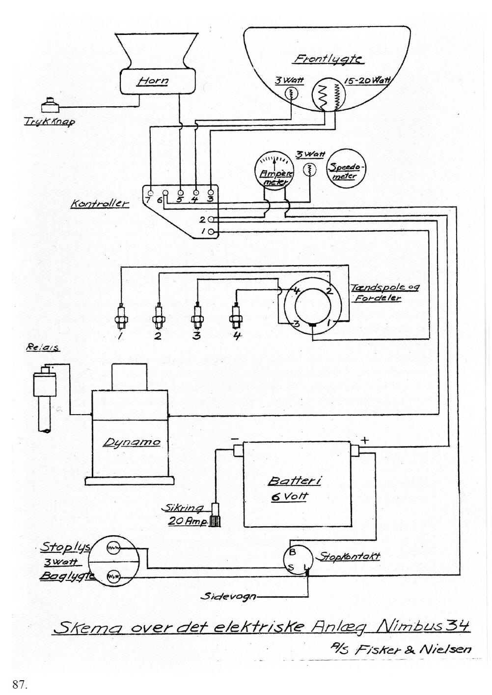
[Translation of page 87] Head light Horn 3 Watt 15-20 Watt Push button 3 Watt Ammeter Speedometer Switch Ignition coil and distributor Relay Dynamo Fuse 20A Battery 6 Volt Brake light 3 Watt Brake switch Rear light Sidecar
Schematic of the electrical installation of Nimbus 34.
A/S Fisker & Nielsen 87.
[End of translation of page 87]
|