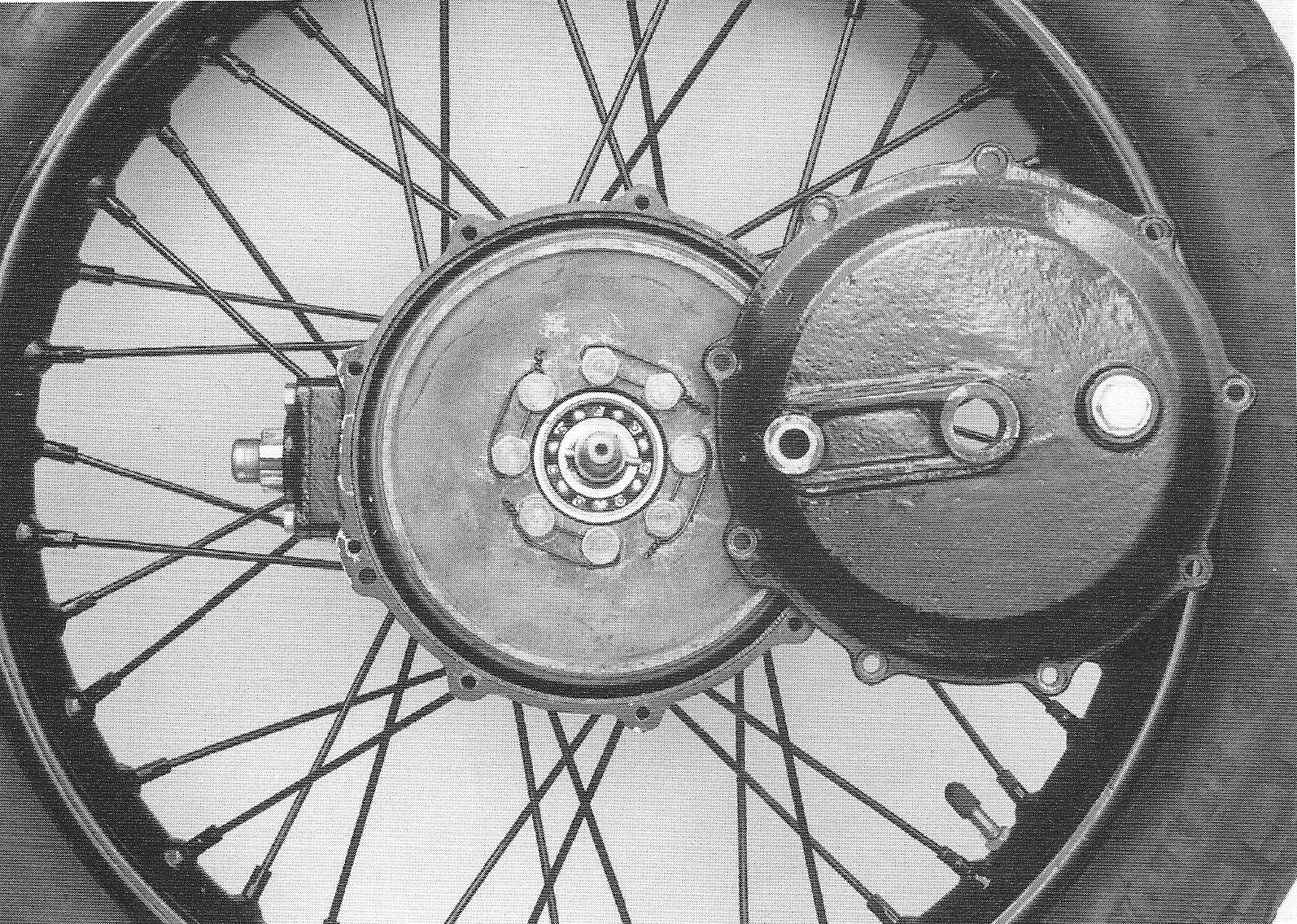
| Rear wheel
The rear wheel has a tyre with a
dimension of 19” x 3½”, a 19” x 3” “Dunlop” rim and a 50 mm hub with
a 150 mm brake drum riveted onto it on the right side.
96.
|
|
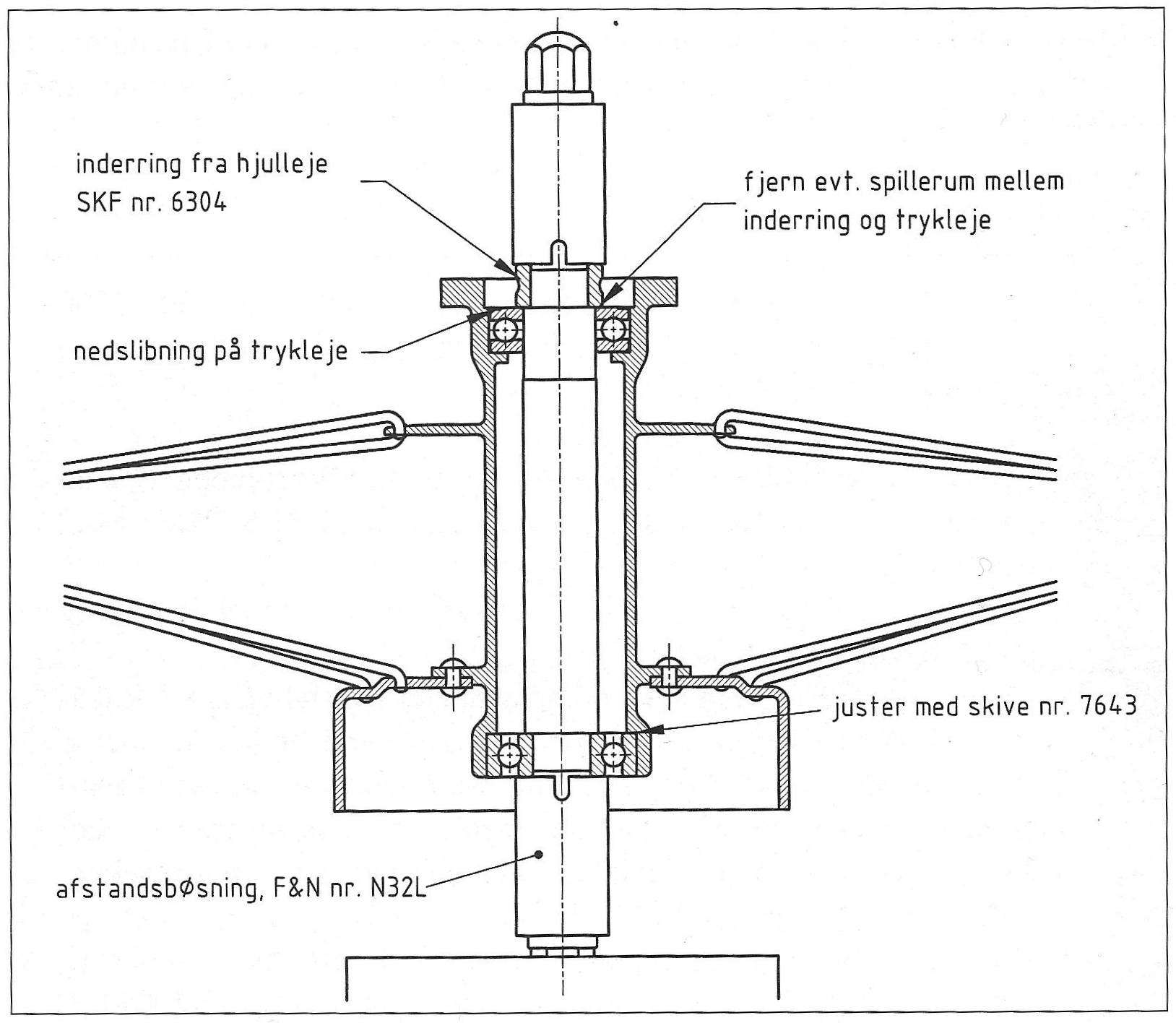
The wheel bearings are two 20 x 52 x 15
mm “SKF” ball bearings, No 6304, and one 25 x 48 x 15.5 mm thrust
bearing “SKF” No 905, to take the axial force of the crown and
pinion wheel. When the rear wheel hub is correctly adjusted, the thrust bearing needs to have some initial loading to prevent axial movement of the rear hub and consequently a change in the adjustment of the crown wheel.
Because it is not commonly known that the rear hub bearings have to be adjusted to No 1301 – 3000, a brief instruction for the adjustment follows below. The adjustment is carried out in the following way: 1. Fit the right bearing on the rear wheel axle and fit the cross pin. Secure the bearing with a distance bush, e.g. F&N N32L/9014-2, and a wheel nut. 2. Secure the wheel nut in a vice with the axle in a vertical position, and fit the rear wheel hub onto the bearing. 3. Fit the thrust bearing. The inner diameter of the two thrust bearing shells are not equal. The shell with the largest diameter, originally with a Ø of 25.2 mm, or alternatively Ø 27 mm, has to face the brake drum. Unfortunately, many rear wheels can be seen with the thrust bearing pointing in the wrong direction, which shouldn’t be possible, but apparently someone succeeded in doing so, using a sufficiently large hammer. 4. Fit the inner ring of a dissembled wheel bearing onto the shaft. Secure the inner ring using a distance bush, e.g. F&N N32L/9014-2, and a wheel nut. 5. It will now be possible to measure the play between thrust bearing and inner ring. If there is any, this clearance has to be relieved by fitting adjustment washers between the right wheel bearing and the wheel hub. Use the same type of adjustment washer, spare part 7643, used at the cover of the pinion wheel. The thrust bearing is correctly adjusted when it has a little initial tension against the inner ring. 6. Remove the inner ring, fit the left hand wheel bearing and start adjusting the crown wheel.
97.
|
| In several rear hubs, even with the original thrust bearing, a clearance up to 0.5 mm between thrust bearing and left wheel bearing was observed and it goes without saying that spending a lot of time in fine-tuning the crown wheel is in vain, if it fails when first ridden, due to the incorrect adjustment of the thrust bearing.
Adjustment of the rear wheel.
The thrust bearing, originally fitted by
Nimbus is about 4 mm wide and 0.3 mm deep at the outer edge of the
upper side of the bearing shell to prevent the bearing from touching
the outer ring of the rear wheel bearing. [Translator’s note: With
the upper side of the bearing, reference is made to the
drawing. In the real world this would not be called the upper
side]
98.
|
| [Translation of the text of the drawing on page 98]
inner
ring of ball bearing ground edge on thrust bearing
adjust with ring No 7643 distance bush, F&N No N32L [End of translation of the text of the drawing on page 98] 98.
|
| Crown and pinion wheel The crown and pinion wheel was unchanged up to No 2561, but due to the introduction of the rubber damped drive shaft the stud of the crown wheel was no longer required. The reduction ratio of the crown and pinion wheel is 4:1 for a solo machine, matching a pinion wheel with 14 teeth and a crown wheel with 56 teeth. For sidecar use a reduction ratio of 4.9:1 is chosen, matching 12 teeth for the pinion wheel and 59 for the crown wheel.
The pinion wheel has an SKF conical
roller bearing 15 x 22 x 16.5 No 30205 at the front and an SKF 15 x
42 x 13 ball bearing No 6302 at the rear.
Crown The gear housing does not have a grease nipple and can be recognised from the continuous threaded holes for the bolts of the pinion wheel’s cover.
99.
|
|
The cover of the crown wheel is attached
to the frame with just one bolt. [Translator’s note: This bolt tends
to loosen, so it is recommended to secure it with Loctite medium
strong]. Apart from the threaded hole for the frame bolt, the cover
has a threaded hole at the rear for the lubrication of the crown and
pinion wheel. This hole is fitted with an 18 mm bolt. The 1934
model’s crown wheel cover was too thin. Many of them have torn or
were later welded around the hole for the rear wheel axle.
The cover for the pinion wheel does not
have the groove for the cork gasket. One can find covers with short
as well as long bushes for the drive shaft. Both types can be seen
in the 1934 brochure, but it is unknown how widely the covers with
long bushes were used.
Rear brake
The front and rear brakes function the same way. The
rear brake lever is located outside the brake drum, and is activated
by the foot brake pedal.
Driveshaft. Rigid driveshaft with a simple spring at one end.
The 1934 model had an almost rigid
transmission between engine and rear wheel, without damping of any
kind. The transmission feels very harsh. It rattles when
accelerating or slowing down, leading to the star shaped keyways of
the clutch, the gearbox, the drive shaft and the pinion wheel to
wear badly. The original transmission system is very rare nowadays, as almost all existing 1934 models have had their clutch or drive shaft replaced by a newer type.
100.
|